
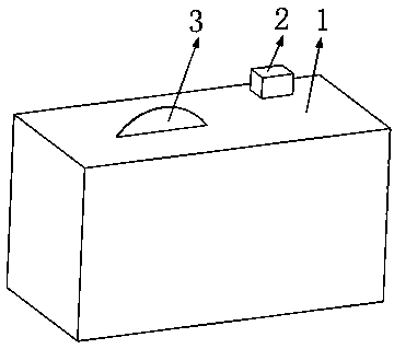
Safety bench saw protecting saw blade

A table saw and saw blade technology, which is applied in the field of safety table saws, can solve the problems of teeth collision and damage, cutting hands, etc.

Inactive Publication Date: 2018-10-12
姚贵友
View PDF0 Cites 0 Cited by
  • Summary
  • Abstract
  • Description
  • Claims
  • Application Information

AI Technical Summary

Problems solved by technology

[0002] At present, for the traditional table saw, the user needs to be careful to use the table saw to cut the object to be cut; but in the process of using it, the user may still cut his hand due to accidents
In order to prevent the user from being cut by accident, there is a hot dog saw in the current technology that is specially designed to protect the user, but the saw blade of the hot dog saw cuts in a very short time In the process of stopping, the saw blade is limited instantly by rigidity; when the saw blade is stopped rapidly by rigid limit many times, the teeth on the saw blade are easily damaged by the collision of rigid limit; at the same time, the traditional hot dog saw The way for the saw blade to return to the table below the saw table in an emergency is realized by the angular momentum of the saw blade; the reliability of the mechanism operation can be guaranteed by increasing the way the saw blade returns to the table below the saw table; In addition, in order to prevent the saw blade from being damaged by the rigid limit collision, it is necessary to design a safety table saw that can protect the saw blade

Method used


Image

  • Safety bench saw protecting saw blade
  • Safety bench saw protecting saw blade
  • Safety bench saw protecting saw blade

Examples


specific Embodiment approach

[0085] Specific embodiments: when the table saw works normally, the trigger powder in the powder chamber 35 has not exploded, and the telescopic rod 12 is perpendicular to the first swing rod 8; the first swing rod 8 and the second swing rod 31 are collinear. The first limiting tooth 22 and the second limiting tooth 24 have no limiting effect. The leaf spring 56 is in a compressed state, the fourth limiting tooth 58 is located in the gap between two adjacent third limiting teeth 51, the third limiting tooth 51 and the fourth limiting tooth 58 produce a limiting effect, and the fourth limiting tooth 58 produces a limiting effect. The second pendulum plate 57 and the fifth U-shaped plate 55 are limited so that the slider 52 cannot slide in the sliding groove 49 . The motor 5 drives the driven wheel 16 to rotate through the drive shaft 14, the drive wheel 6 and the belt 15; the driven wheel 16 drives the ring saw blade 3 to rotate through the drive ring 25 and the ring sleeve 17....


PUM


Abstract

The invention belongs to the technical field of bench saws and particularly relates to a safety bench saw protecting a saw blade. The safety bench saw comprises a bench saw shell, a controller, a ring-shaped saw blade, a motor, a drive wheel, a first U-shaped plate, a first swing rod, an arc-shaped guide rail, a telescoping rod, a belt, a driven wheel and the like. After explosive is triggered andexplodes, a ring sleeve moves to the direction of the first U-shaped plate instantly, and then the ring-shaped saw blade is away from the hand and enters a mechanism cavity completely; in the processof moving to the direction of the first U-shaped plate of the ring sleeve, a first limiting tooth and a second limiting tooth generate limitation, and the ring-shaped saw blade stops rotating instantly; and the ring-shaped saw blade stops rotating, the ring-shaped saw blade is away from the hand and enters the mechanism cavity completely, and in this way, harm risks caused by further contact withthe ring-shaped saw blade of the hand is reduced. In addition, when the driven wheel moves in the direction of a triangle block instantly, the belt gets loose gradually, the possibility that the driven wheel still enables the ring-shaped saw blade to rotate after being subjected to transmitting is avoided, and safety of users is protected.

Description

technical field [0001] The invention belongs to the technical field of table saws, in particular to a safety table saw for protecting saw blades. Background technique [0002] At present, for the traditional table saw, the user needs to use the table saw carefully to cut the object to be cut; however, in the process of using the table saw, the hand of the user may still be cut due to accidents. In order to prevent the user from being cut by accident, there is a hot dog saw in the current technology that is specially designed to protect the user, but the saw blade of the hot dog saw cuts in a very short time In the process of stopping, the saw blade is limited instantly by rigidity; when the saw blade is stopped rapidly by rigid limit many times, the teeth on the saw blade are easily damaged by the collision of rigid limit; at the same time, the traditional hot dog saw The way for the saw blade to return to the table below the saw table in an emergency is realized by the ang...

Claims


Application Information

Patent Timeline
IPC IPC(8): B23D45/06
CPCB23D45/06
Inventor 徐桂娣
Owner 姚贵友
Learn More