Automatic disassembling system for bogie bearing spring

A bogie and guide rail technology, which is applied in metal processing, metal processing equipment, manufacturing tools, etc., can solve the problems of low work efficiency and high labor intensity, and achieve the effect of reducing labor intensity and improving disassembly efficiency

Active Publication Date: 2018-10-12
SOUTHWEST JIAOTONG UNIV
View PDF10 Cites 18 Cited by
  • Summary
  • Abstract
  • Description
  • Claims
  • Application Information

AI Technical Summary

Problems solved by technology

[0005] The object of the present invention is: in order to solve the problems of high labor intensity and low work efficiency caused by manual removal of the load spring and the wedge block during the disassembly process of the existing bogie, the present invention provides a Bogie Carrying Spring Automatic Dismounting System

Method used


Image

  • Automatic disassembling system for bogie bearing spring
  • Automatic disassembling system for bogie bearing spring
  • Automatic disassembling system for bogie bearing spring

Examples


Embodiment 1

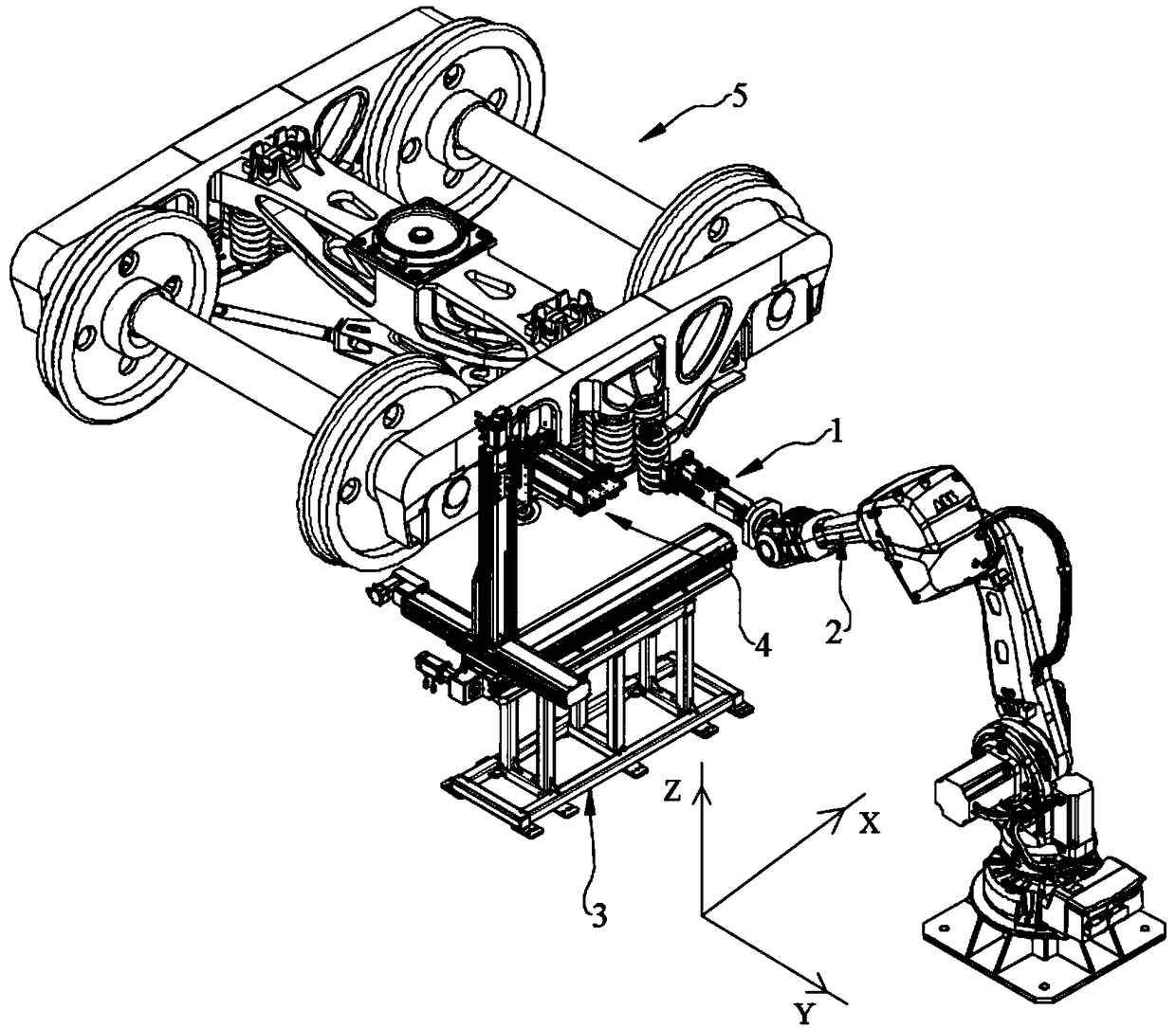
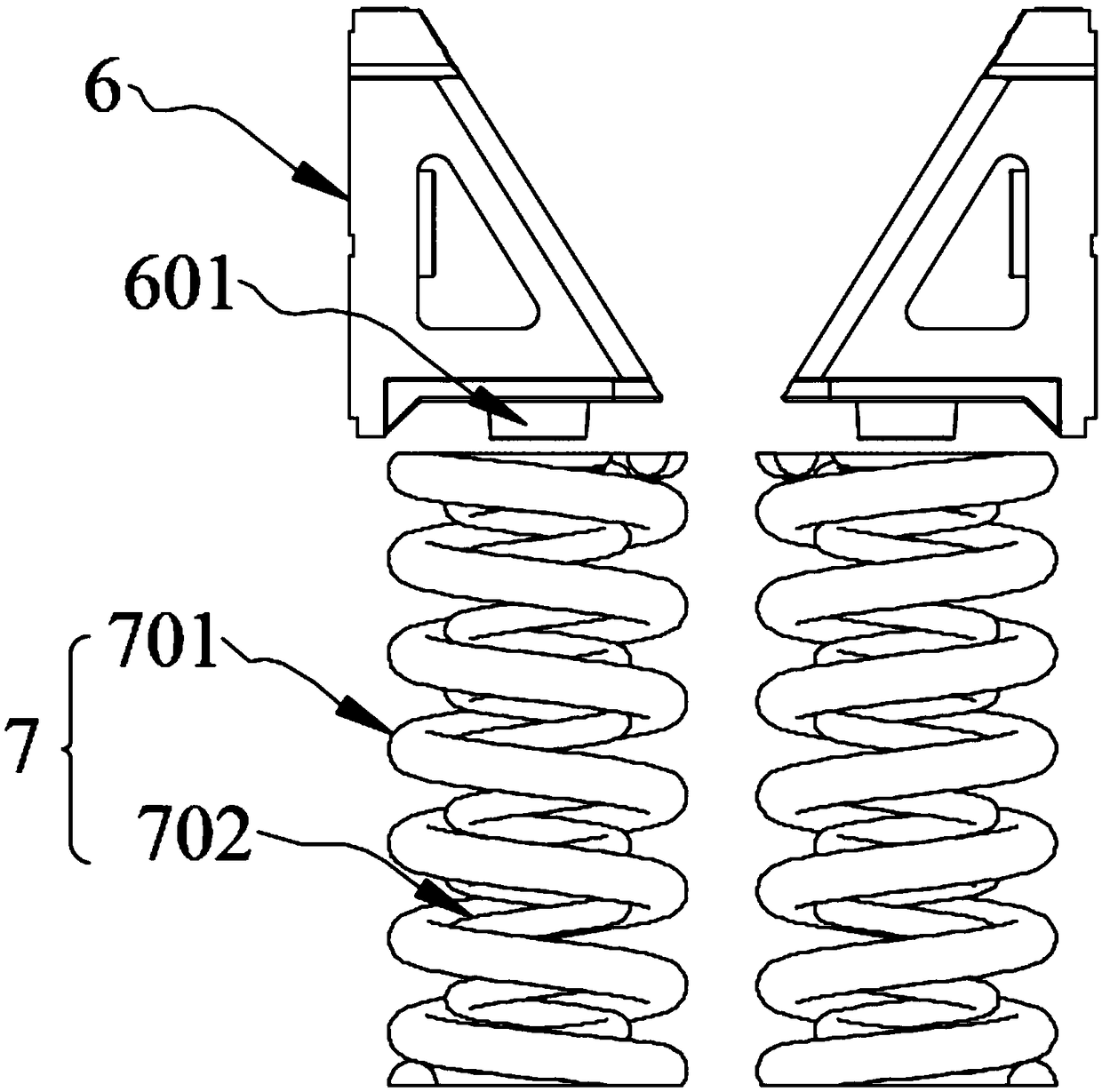
[0046] as attached figure 1 As shown in and , the bogie 5 carrying spring 7 automatic dismounting system of the present invention includes a jacking device and a clamping device; the jacking device includes a jacking unit 4 for taking out the wedge block 6, and the jacking unit 4 is connected with a three-axis cantilever, and the gripping device includes a gripper 1 for gripping the bearing spring 7, and the gripper 1 is connected with a mechanical arm 2.

[0047] In this embodiment, the space movement of the jacking device is realized by the three-axis cantilever, and the wedge block 6 is first taken out through the jacking device; Take out, in the process of taking out the wedge block 6 and the bearing spring 7, the manpower only needs to operate the equipment to move the jacking device to the approximate position relative to the wedge block 6, and move the chuck 1 to the middle part of the bearing spring 7 and then The mechanical automation will take out the wedge block 6 ...

Embodiment 2

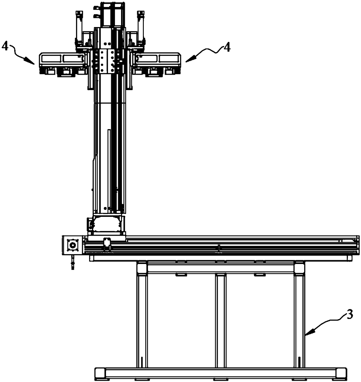
[0049] as attached Figure 3-4 As mentioned above, this embodiment is optimized as follows on the basis of Embodiment 1: the three-axis cantilever includes an X-axis guide rail 801, a Y-axis guide rail 802, and a Z-axis guide rail 803 each equipped with a ball screw. The lower end of the cantilever is provided with a bracket 3, the X-axis guide rail 801 is horizontally arranged on the upper end of the bracket 3, the Y-axis guide rail 802 is horizontally arranged on the upper end of the X-axis guide rail 801 and is perpendicular to the X-axis guide rail, and the middle part of the Y-axis guide rail 802 The lower end is connected with a first sliding seat 8011, the first sliding seat 8011 is connected with the X-axis guide rail 801, the upper end of the Y-axis guide rail 802 is vertically connected with a Z-axis guide rail 803, and the lower end of the Z-axis guide rail 803 is connected with The second sliding seat 8021 is connected to the Y-axis guide rail 802 . The X-axis guid...

Embodiment 3

[0052] as attached Figure 5-6 As shown, this embodiment is based on Embodiment 2 and is optimized as follows: the Z-axis guide rail 803 is also connected with a third sliding seat 8031, and the jacking unit 4 is provided with two 803 is symmetrical, the two jacking units 4 are connected to the third sliding seat 8031; the jacking unit 4 includes a laser sensor, a connecting plate 401, a jacking platform 403, a jacking rod 406 and a small cylinder 407, so The connecting plate 401 connects the jacking platform 403 and the third sliding seat 8031 ​​with each other. The upper end of the jacking platform 403 is provided with a laser sensor, and the middle part of the lower end of the jacking platform 403 is provided with a lifting plate 405. The lifting plate 405 is provided with a U-shaped card slot, and the left and right sides of the lifting plate 405 are provided with jacking rods 406. The front end of the lifting rod 406 is located in front of the front end of the jacking pla...


PUM


Abstract

The invention discloses an automatic disassembling system for a bogie bearing spring and belongs to the technical field of bogie disassembling device. The problems that in the existing bogie disassembling process, both a bearing spring and an inclined wedge block need taken out in a manual carrying mode, thus, the labor intensity is high, and the working efficiency is low are solved. The automaticdisassembling system comprises a jacking device and a clamping device; the jacking device comprises a jacking unit used for taking an inclined wedge block out, and the jacking unit is connected witha three-axis cantilever; and the clamping device comprises a clamping head for clamping the bearing spring, and the clamping head is connected with a mechanical arm.

Description

technical field [0001] The invention relates to the technical field of bogie dismantling, and more particularly relates to an automatic dismantling system for bogie bearing springs. Background technique [0002] The bogie is one of the most important components in the rail vehicle structure, and various parameters of the bogie also directly determine the stability of the vehicle and the ride comfort of the vehicle. During the maintenance of the bogie, the structure needs to be disassembled. The load springs are mainly removed by manual movement. The load springs at both ends of the bogie are divided into three rows: outer, middle and inner. There are differences in the number and type of load-bearing springs, and the pitch of the load-bearing springs is also different. A load-bearing spring includes an inner load-bearing spring and an outer load-bearing spring, and the inner load-bearing spring and the outer load-bearing spring are independent of each other. When carrying t...

Claims


Application Information

Patent Timeline
Patent Type & Authority Applications(China)
IPC IPC(8): B23P19/00
CPCB23P19/00
Inventor 刘桓龙李顺焦万均蒋越
Owner SOUTHWEST JIAOTONG UNIV
Why Eureka
Try Eureka