Die cutting device for building

A construction and die-cutting technology, applied in metal processing and other directions, can solve the problems of low working efficiency of die-cutting machines and the inability of continuous die-cutting of die-cutting machines, and achieve the effects of novel design, high degree of automation, and improved work efficiency.

Active Publication Date: 2018-10-12
安徽屹筑建设工程有限公司
View PDF13 Cites 14 Cited by
  • Summary
  • Abstract
  • Description
  • Claims
  • Application Information

AI Technical Summary

Problems solved by technology

[0003] Die-cutting machines are widely used in the production process. The existing die-cutting machines cannot perform fast and continuous die-cutting, resulting in low working efficiency of the die-cutting machines.

Method used


Image

  • Die cutting device for building
  • Die cutting device for building
  • Die cutting device for building

Examples


Embodiment Construction

[0018] The technical solutions in the embodiments of the present invention will be clearly and completely described below in conjunction with the accompanying drawings in the embodiments of the present invention. Obviously, the described embodiments are only a part of the embodiments of the present invention, rather than all the embodiments. Based on the embodiments of the present invention, all other embodiments obtained by those of ordinary skill in the art without creative work shall fall within the protection scope of the present invention.

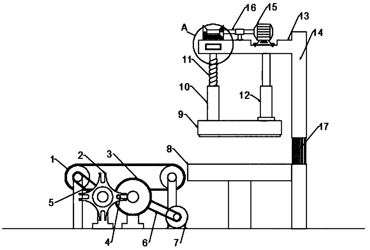
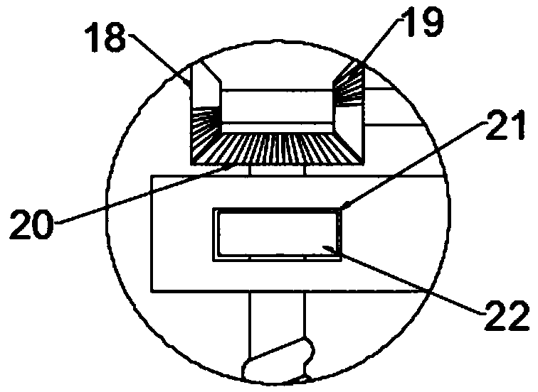
[0019] See Figure 1~3 In the embodiment of the present invention, a die cutting device for construction includes an intermittent conveying mechanism, a workbench 8, a die cutting mechanism, and a bracket 14. The intermittent conveying mechanism is arranged at the left end of the workbench 8, and the intermittent conveying mechanism The upper end surface of the conveyor belt is at the same level as the table surface of the worktable 8. T...


PUM


Abstract

The invention discloses a die cutting device for a building. The die cutting device comprises an intermittent conveying mechanism, a worktable, a die cutting mechanism and a bracket. The die cutting device for the building disclosed by the invention is novel in design. A first motor rotates to drive a rotary disc to rotate through a second belt, and the rotary disc drives a conveyor belt to rotateintermittently under the action of a Maltese wheel and a first belt so as to achieve an intermittent feeding process. A second motor rotates to drive a rotary shaft to rotate, and the rotary shaft drives an incomplete bevel gear A and an incomplete bevel gear B to rotate. When a toothed part on the incomplete bevel gear A is engaged to a bevel gear, a threaded rod rotates. When the toothed part on the incomplete bevel gear A is far from the bevel gear and a toothed part of the incomplete bevel gear B is engaged to the bevel gear, the threaded rod rotates reversely, so that the threaded rod rotates forward and backward in a reciprocating manner. The threaded rod drives a die cutting head to move up and down in the reciprocating manner through a threaded bushing, so that continuous die cutting is achieved, the degree of automation is high and the work efficiency is improved.

Description

Technical field [0001] The invention relates to the field of construction equipment, in particular to a die cutting device for construction. Background technique [0002] Die-cutting machine is also called beer machine, cutting machine, CNC punching machine, which is mainly used for die-cutting of corresponding non-metallic materials, stickers, EVA, double-sided tape, electronics, mobile phone pads, etc. Cutting), indentation and hot stamping operations, laminating, automatic waste removal, die-cutting machine uses steel knives, metal molds, steel wire (or steel plate engraved template), through the imprint plate to apply a certain pressure, the printed product or The paperboard is rolled into a certain shape, which is an important equipment for post-press packaging processing. The working principle of the die-cutting machine is to use die-cutting knives, steel knives, metal molds, steel wires (or stencils carved from steel plates) through embossing plates Apply a certain pressu...

Claims


Application Information

Patent Timeline
Patent Type & Authority Applications(China)
IPC IPC(8): B26F1/40B26D7/06
CPCB26D7/0625B26F1/40
Inventor 刘辉辉
Owner 安徽屹筑建设工程有限公司
Why Eureka
Try Eureka