
Tyre separation device of tyre transportation line

A separation device and conveying line technology, applied in the direction of conveyor objects, transportation and packaging, roller table, etc., can solve the problems of unable to complete the separation of tires, easy to be clamped between two arms and so on

Active Publication Date: 2018-10-12
DONGFENG LIUZHOU MOTOR
View PDF7 Cites 5 Cited by
  • Summary
  • Abstract
  • Description
  • Claims
  • Application Information

AI Technical Summary

Problems solved by technology

The tire separation device of this tire conveying line has the following disadvantages in the production process: when the conveyed tires have a large difference in diameter, the small-diameter tires will easily be caught between the two arms when they touch the arms, and even fall from the two arms. Continue to run forward through the middle of the arms, unable to complete tire separation
The tire separation device of this tire conveying line is not suitable for conveying and separating tires with large diameter differences

Method used


Image

  • Tyre separation device of tyre transportation line
  • Tyre separation device of tyre transportation line
  • Tyre separation device of tyre transportation line

Examples


Embodiment 1

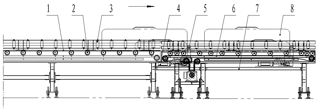
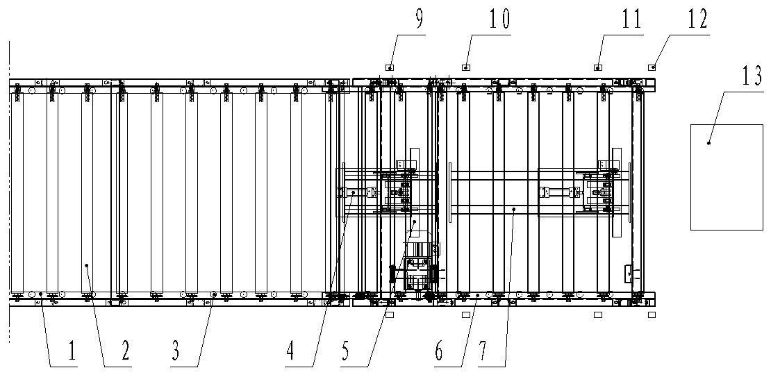
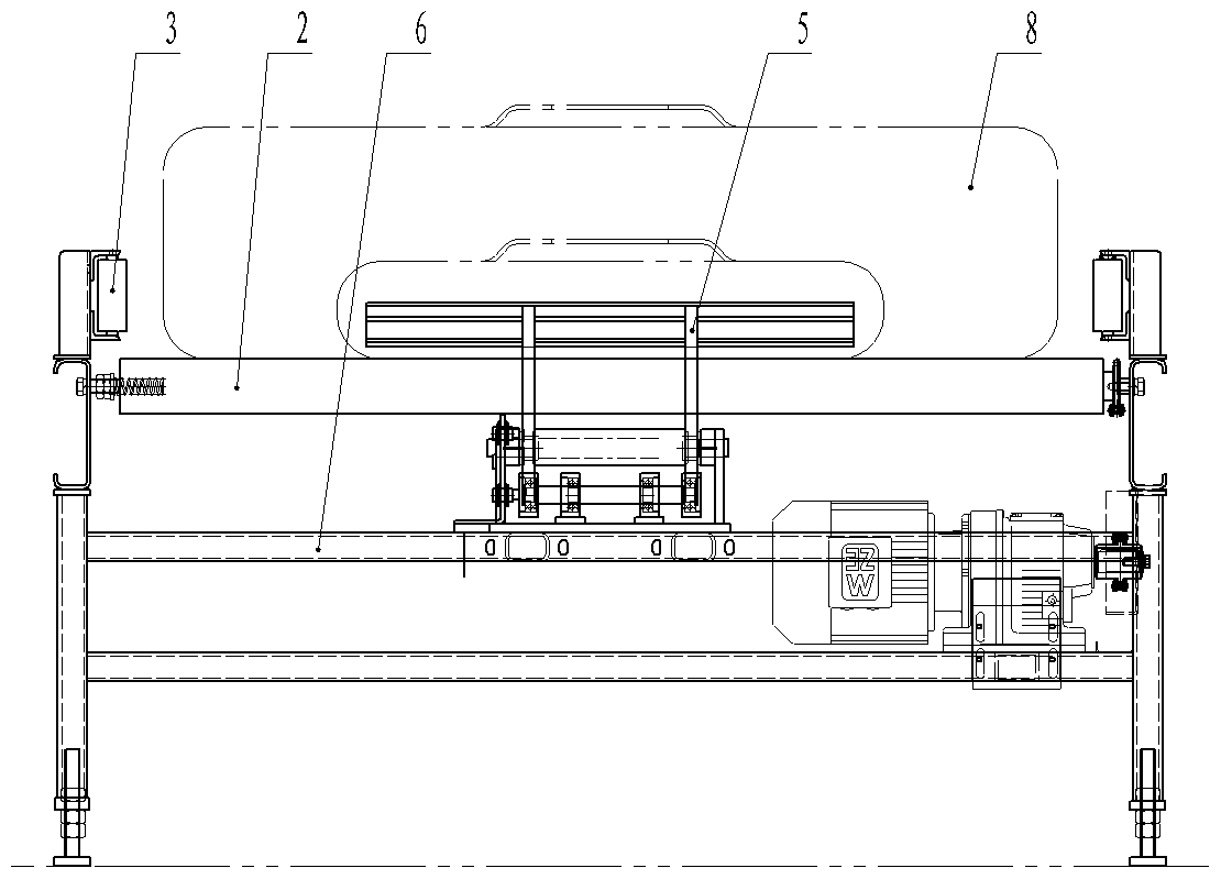
[0032] Such as figure 1 , figure 2 , image 3 The tire separation device of a tire conveying line shown includes a main conveying roller table 1, and the output end of the main conveying roller table 1 is connected with a high-speed roller table 6 for separating individual tires, and the conveying surface of the high-speed roller table 6 is lower than The conveying surface of the main conveying roller table 1 is 8mm. Both sides of the main conveying roller table 1 and the high-speed roller table 6 are equipped with guide guardrails, and the guide guardrails are composed of vertically arranged guide rollers 3 . Hook-type stoppers are respectively installed under the feeding end and the discharging end near the high-speed roller table 6, such as Figure 4 , Figure 5 , Figure 6The shown hook stopper has a retaining arm part 5 that is rotatably connected to the frame 7, and the frame 7 is equipped with a power cylinder 4 that drives the retaining arm part 5 to rotate and s...

Embodiment 2

[0038] The difference between this embodiment and Embodiment 1 is that: the conveying surface of the high-speed roller table 6 is 12 mm lower than the conveying surface of the main conveying roller table 1; other features are the same as in Embodiment 1.


PUM


Abstract

The invention discloses a tyre separation device of a tyre transportation line and relates to the technical field of automatic production. The tyre separation device of the tyre transportation line comprises a main rollgang, wherein a high speed roller bed for transporting single tyres is hinged to the output end of the main rollgang, hook type stoppers are separately arranged at the feed inlet and the discharge end of the high speed roller bed, each hook type stopper is provided with a barrier arm part rotatably connected to a rack, and a power cylinder which drives the barrier arm part to stretch out of the transportation surface of the high speed roller bed is mounted on the rack; a first stand-out switch and a first occupied switch are separately arranged on front and back sides of thebarrier arm part located at the feed inlet, a second stand-out switch and a second occupied switch are separately arranged on front and back sides of the barrier arm part located at the discharge end, and the power cylinder, the first occupied switch, the second occupied switch, the first stand-out switch and the second stand-out switch are electrically connected to a control box. Compared with the prior art, the tyre separation device can separate tyres, the diameters phi of which are 750mm to 1300mm on the transportation line, and the tyre separation device is suitable for transporting andseparating tyres, the diameter difference of which is relatively great.

Description

technical field [0001] The invention relates to the technical field of automobile production, in particular to a tire separating device of an automobile tire conveying line. Background technique [0002] Modern automobile production usually uses a tire conveyor line to transport tires. The tires are arranged next to each other in a string on the conveyor line. It is often necessary to separate the tires one by one and transport them to the designated location separately. There is an existing tire separation device for a tire conveying line, which includes a main conveying roller table driven by a motor, and an arm-embracing stopper is provided near the output end of the main conveying roller table. The arm-embracing stopper has a Two arm arms are arranged opposite to each other above the conveying surface. The two arms are respectively hinged on the frame on both sides of the main conveying roller table. Each arm is connected to the cylinder that drives it to rotate. The fi...

Claims


Application Information

Patent Timeline
IPC IPC(8): B65G13/00B65G47/24B65G47/88
CPCB65G13/00B65G47/24B65G47/88
Inventor 银立越黄佳华文建东李昆霖
Owner DONGFENG LIUZHOU MOTOR
Learn More