A hoisting device applied to shared equipment of electric power towers

A technology for electric power towers and shared equipment, which is applied in the direction of hoisting equipment safety devices, lifting devices, etc., and can solve problems such as inability to save time and effort in sharing equipment

Active Publication Date: 2020-03-06
YUNNAN POWER GRID CO LTD ELECTRIC POWER RES INST
View PDF4 Cites 1 Cited by
  • Summary
  • Abstract
  • Description
  • Claims
  • Application Information

AI Technical Summary

Problems solved by technology

[0005] This application provides a hoisting device applied to shared equipment of electric power towers, to solve the technical problem in the prior art that it is impossible to save time and labor, and safely and effectively install shared equipment on electric power towers

Method used


Image

  • A hoisting device applied to shared equipment of electric power towers
  • A hoisting device applied to shared equipment of electric power towers
  • A hoisting device applied to shared equipment of electric power towers

Examples


Embodiment Construction

[0029] In order to enable those skilled in the art to better understand the technical solutions in the present application, the technical solutions in the embodiments of the present application will be clearly and completely described below in conjunction with the drawings in the embodiments of the present application. Obviously, the described The embodiments are only some of the embodiments of the present application, not all of them. Based on the embodiments in this application, all other embodiments obtained by persons of ordinary skill in the art without creative efforts shall fall within the scope of protection of this application.

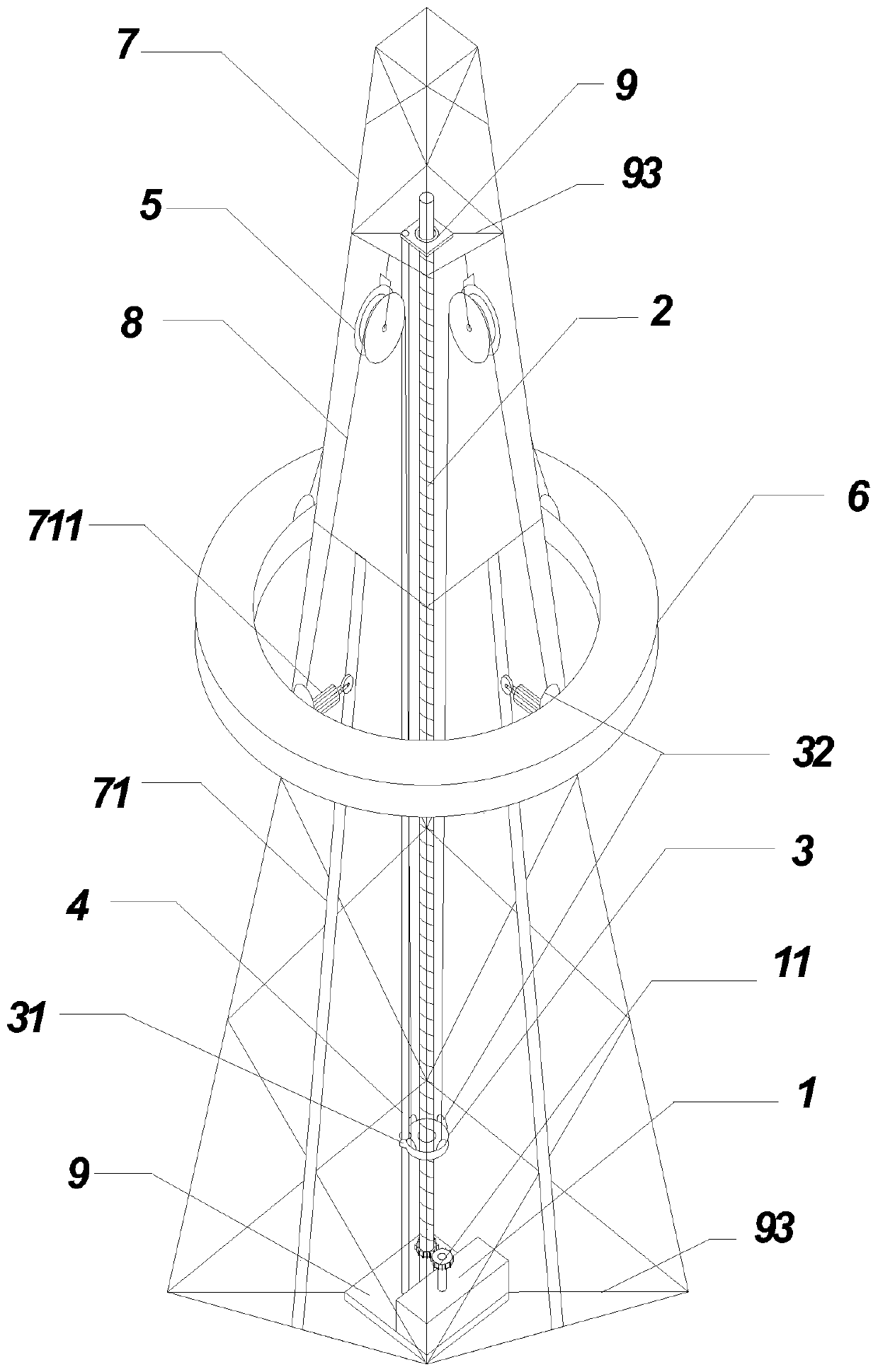
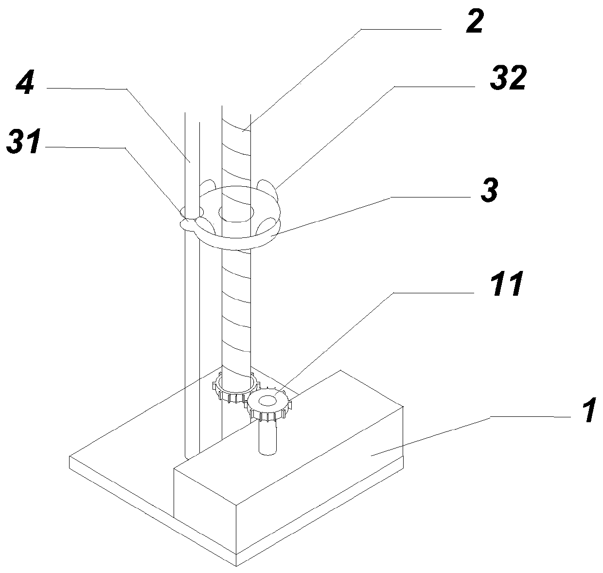
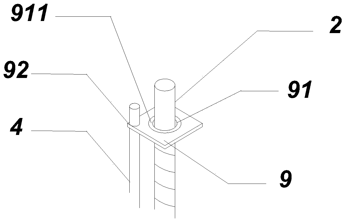
[0030] see figure 1 , is a schematic diagram of the basic structure of a lifting device applied to electric power tower sharing equipment provided by an embodiment of the present invention. combine figure 1 It can be obtained that the lifting device provided in the present application includes: a driver 1 , a screw rod 2 , a threaded slidin...


PUM


Abstract

The invention discloses a loading and hanging device applied to electric iron tower shared equipment. The loading and hanging device comprises a driving device, a screw, a threaded sliding sleeve, a positioning shaft, fixed pulleys and a loading platform; wherein the screw is overlapped at the central axis of an electric iron tower, one end of the screw is connected with the driving device througha transmission gear, and the other end of the screw is connected with the top of the electric iron tower and the screw rotates along the central axis; the transmission gear is located at the bottom of the electric iron tower, the positioning shaft is parallel to the screw, and the two ends of the positioning shaft are fixed at the bottom and the top of the electric iron tower correspondingly; thethreaded sliding sleeve is arranged on the screw in a sleeving mode, a sliding hole is formed in the threaded sliding sleeve, and the positioning shaft is arranged in the sliding hole in a sleeved mode; the fixed pulleys are arranged at the central line of the side surface of the electric iron tower and are all located at the top of the electric iron tower; and each of the quartering points of the loading platform is connected with one end of each of wire ropes, and the other end of each of the wire ropes passes through the corresponding fixed pulley and is connected to the corresponding quartering point of the threaded sliding sleeve. According to the loading and hanging device applied to the electric iron tower shared equipment, the process of climbing and installing of operators is replaced, the later detection and maintenance are facilitated, time and effort are saved, and safety and efficiency are achieved.

Description

technical field [0001] The present application relates to the technical field of hoisting, and in particular to a hoisting device applied to shared equipment of electric power towers. Background technique [0002] In recent years, the sharing economy has continued to rise, and in the power and communication industries, the sharing of power towers is increasingly developing. The shared power tower is to install communication base stations, monitoring, photovoltaic or wind power equipment on the power tower under the premise of fully ensuring the safety of the power grid and the quality of communication. The above equipment can be called shared equipment. From a practical point of view, sharing power towers can save land, time and cost. It is an innovative move to speed up the construction of a resource-saving and environment-friendly society and realize "complementary advantages, win-win cooperation, and harmonious development" of state-owned assets. [0003] The installatio...

Claims


Application Information

Patent Timeline
Patent Type & Authority Patents(China)
IPC IPC(8): B66F11/04B66F17/00
CPCB66F11/04B66F17/006
Inventor 魏少敏黄星彭晶谭向宇王科
Owner YUNNAN POWER GRID CO LTD ELECTRIC POWER RES INST
Why Eureka
Try Eureka