A New Water Level Sensor Applied in Washing Machine

A technology of water level sensor and washing machine, applied in the control device of washing machine, other washing machines, applications, etc., can solve the problems of washing machine with water and dehydration, poor terminal contact, short circuit fault, etc., to avoid washing with empty bucket or with water and dehydration, avoid Effects of poor contact and avoidance of patina

Active Publication Date: 2022-04-26
FOSHAN SHUNDE HAIER ELECTRIC APPLIANCES CO LTD +1
View PDF8 Cites 0 Cited by
  • Summary
  • Abstract
  • Description
  • Claims
  • Application Information

AI Technical Summary

Problems solved by technology

[0003] Because the water level sensor is used in a humid environment, it will cause condensation on the coil and the shell, and water droplets will form on the surface, which will cause the water level sensor to form a capacitive effect, and the two terminals of the water level sensor will have a short circuit fault, which will affect the output frequency.
In addition, the terminals of the connectors are affected by the humid environment to produce a patina phenomenon, and the terminals of the water level sensor are not in good contact, so that the washing machine appears to be washed in an empty bucket or dehydrated with water.

Method used


Image

  • A New Water Level Sensor Applied in Washing Machine
  • A New Water Level Sensor Applied in Washing Machine
  • A New Water Level Sensor Applied in Washing Machine

Examples


Embodiment 1

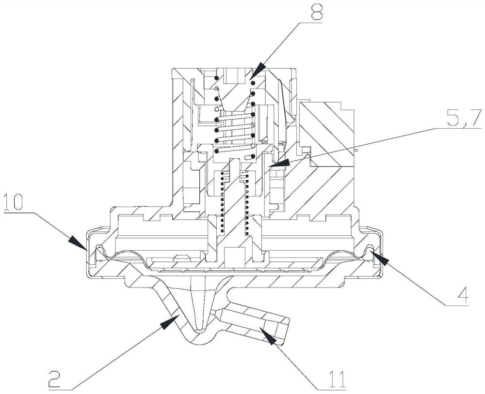
[0036] Such as Figure 1 to Figure 4 As shown, a new type of water level sensor 100 is introduced in this embodiment, which includes a housing 1, an air cover 2, an adjusting screw receiving plate 3, and a rubber diaphragm 4 is installed in the chamber surrounded by the housing 1 and the air cover 2, and the rubber diaphragm 4 Divide the chamber into upper and lower chambers, the lower chamber is the air intake cavity, which communicates with the air intake nozzle 11 provided on the gas cover 2; the upper chamber is equipped with a coil unit, and the coil unit It includes a coil shaft 5 , an inductance coil 7 and at least two terminals 6 .

[0037]In this embodiment, the bottom of the gas cover 2 and the housing 1 is fixedly connected by a riveting ring 10, and a rubber diaphragm 4 is installed in the chamber surrounded by the gas cover 2 and the housing 1, and one side of the rubber diaphragm 4 is connected to the intake air. The other side of the diaphragm is connected to t...

Embodiment 2

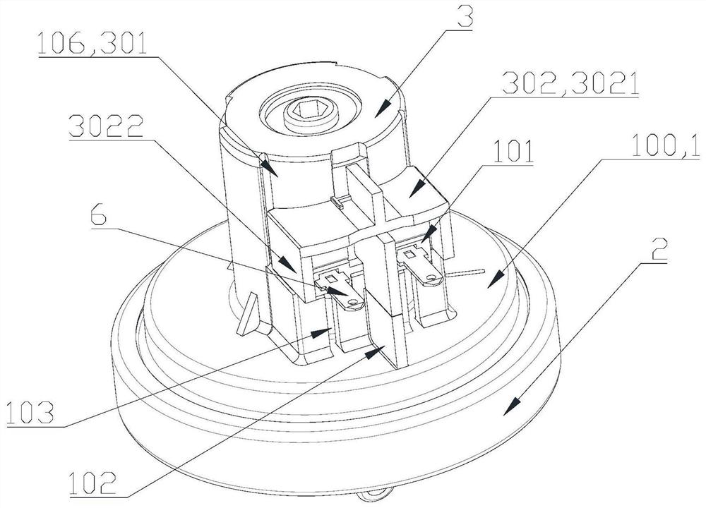
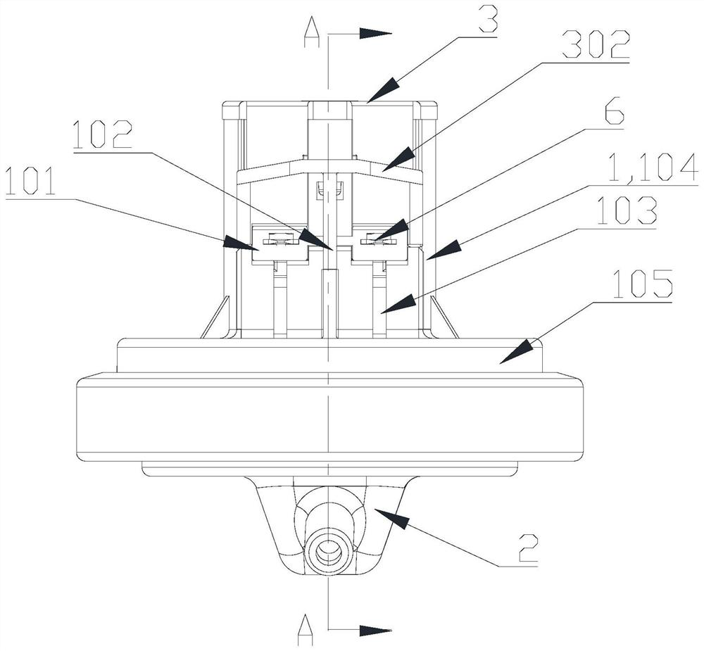
[0040] Such as Figure 1 to Figure 4 As shown, a new type of water level sensor 100 is introduced in this embodiment, which includes a housing 1, an air cover 2, and an adjusting screw receiving plate 3. A coil unit is installed in the chamber surrounded by the housing 1 and the air cover 2, and the coil unit includes The coil shaft 5, the inductance coil 7 and at least two terminals 6; the housing 1 is provided with an insertion interface 101, and the terminals 6 protrude from the insertion interface 101 of the housing 1, and are all fixed on the same side of the housing 1, and the housing 1 A baffle 102 located in the middle of adjacent terminals 6 is provided on the outer wall to separate adjacent terminals 6 , so as to ensure mutual insulation between adjacent terminals 6 and avoid short circuit of terminals 6 caused by dew condensation on housing 1 .

[0041] In this embodiment, the sockets 101 are arranged adjacent to each other in parallel and at the same height. The te...

Embodiment 3

[0043] Such as Figure 1 to Figure 4 As shown, in this embodiment, the outer wall of the housing 1 is provided with a protective cover 302 located above the terminal 6, and the protective cover 302 is placed horizontally, parallel to the terminal, and extends outward. Condensation formed on the casing 1 due to high humidity will gather on the protective cover 302 , and under the action of gravity, the condensation will flow to the base 105 of the casing 1 . By setting the protective cover 302, the condensation generated by the housing 1 above the terminal 6 will not gather on the terminal 6, avoiding the copper green phenomenon of the terminal 6 affected by the humid environment, thereby avoiding the occurrence of poor contact of the terminal 6 , further avoiding the washing machine with an empty bucket or dehydration with water.

[0044] In this embodiment, the top of the housing 1 is provided with an opening, and the adjusting screw receiving plate 3 is inserted into the in...


PUM


Abstract

The invention discloses a new type of water level sensor, which comprises a housing, an air cover, and an adjusting screw receiving plate. A coil unit is installed in a chamber surrounded by the housing and the air cover. The coil unit includes at least two terminals, and the terminals are separated from the housing The sockets of the two terminals protrude and are fixed on the same side of the housing. The outer wall of the housing is provided with a baffle in the middle of the adjacent terminals to separate the adjacent terminals. The present invention also discloses a washing machine, on which the water level sensor described above is installed, and the water level sensor communicates with the air chamber of the washing machine. By arranging a baffle plate located in the middle of adjacent terminals on the housing, mutual insulation between adjacent terminals is ensured, and short circuit of the terminals caused by dew condensation on the housing is avoided.

Description

technical field [0001] The invention belongs to the technical field of washing machines, and in particular relates to a novel water level sensor and a washing machine using the novel water level sensor. Background technique [0002] The water level sensor in the prior art is a type of sensor used to detect water level information and convert the water level into an electrical signal. It includes a gas cover, a housing, a diaphragm, an iron core, a main spring and a coil unit. The lower part of the housing is equipped with a fluid pressure sensor. receiving room. The water pressure is transmitted to the sensor air chamber through the air pipe, and the diaphragm overcomes the rebound force of the main spring to move the knife core to the coil direction under the action of the air pressure. When the core moves inside the coil, the inductance of the coil corresponds to the displacement of the core The water level sensor transmits this linear change to the computer board of the ...

Claims


Application Information

Patent Timeline
Patent Type & Authority Patents(China)
IPC IPC(8): D06F39/08D06F33/42
CPCD06F39/083D06F39/087D06F2103/18D06F33/42
Inventor 陈瑜薛凯高秋英
Owner FOSHAN SHUNDE HAIER ELECTRIC APPLIANCES CO LTD
Why Eureka
Try Eureka