Flexible current sensor with stranded core

a flexible current sensor and core technology, applied in the direction of voltage/current isolation, magnetic field magnitude/direction, measurement devices, etc., can solve the problem that the accuracy of state of the art flexible rogowski current sensor is still insufficient for precision metering applications, and affects the accuracy of flexible current sensors. problem, to achieve the effect of improving the overall flexibility of the sensor, improving the cross-sectional area accuracy, and ensuring long-term dimensional and thermal stability

Active Publication Date: 2020-08-04
GRHACEK OVER NO LADISLAV
View PDF15 Cites 0 Cited by
  • Summary
  • Abstract
  • Description
  • Claims
  • Application Information

AI Technical Summary

Benefits of technology

[0013]The plurality of individual fibers of the flexible core improves the accuracy of cross-sectional area of the flexible core due to averaging of individual fiber diameter deviations and improves the overall flexibility of the sensor. Fibers fabricated from the metallic material ensure long term dimensional and thermal stability due to generally better mechanical and thermal properties of metal compared to flexible plastics. The linearity of the current sensor is ensured by utilizing a non-magnetic metal. The isolating layer covering individual conductive metallic wires of the core ensures mutual insulation of the wires and therefore prevents circular core current from affecting the current measurement accuracy. As a suitable nonmagnetic metal it is possible to use, for example, aluminum or copper.
[0014]The separation layer from a nonconductive material located between sensing coil windings ensures low coil capacitance and thus a wider frequency range of the sensor. Preferably, the separation layer is made from a nonmetallic fiber winding. The fiber winding ensures accurate layer thickness and a simple manufacturing process. A multilayer winding with the altered winding direction compensates the tangential moments produced by the tension of the winding fibers and this way prevents torsion of the final sensor. Preferably, a homogenization foil wrapping the winding ensures a smooth base for accurate winding of the next layer and thus improves the final accuracy and the long-term stability.

Problems solved by technology

The accuracy of flexible current sensors is significantly affected by stability sensor coil inductance.
The accuracy of the state of the art flexible Rogowski current sensors is still insufficient for precision metering applications.

Method used


Image

  • Flexible current sensor with stranded core

Examples


embodiment

An Example of a Possible Embodiment

[0016]The presented example is provided for the purpose of illustration only. Those skilled in the art can suggest plurality of modifications of the presented solution which are covered by the claims.

example

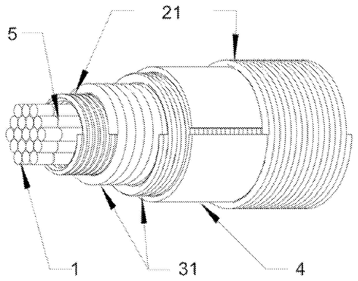
[0017]The presented FIGURE shows a flexible current sensor with a flexible core 1 comprising a plurality of individual fibers from a nonmagnetic material arranged into the nearest hexagonal approximation of a cylindrical shape. A sensing coil 21 comprises an overlapping winding pair wound on the core. Two individual windings of the pair are wound in mutually opposite directions. The separation layer 31 is made of two windings of a nonmetallic fiber wound with mutually opposite directions between the windings of the sensing coil 21. The homogenization foil 4 wrapping the upper winding of the separation layer 31 enables smooth and accurate winding of the outer winding of the sensing coil 21. Each individual fiber of the flexible core 1 is fabricated from a nonmagnetic metallic material and is covered by an isolation layer 5. An enameled copper wire is used in this example as the nonmagnetic metallic material.


PUM


Abstract

A flexible current sensor comprising a sensing coil wound on a cylindrical flexible core where the sensing coil comprises two in series connected overlapping windings wound along the cylindrical flexible core in mutually opposite direction. The cylindrical flexible core comprises a plurality of individual fibers from a nonmagnetic material arranged into the nearest approximation of a cylindrical shape and the sensing coil is equipped with a nonconductive separation layer located between its windings.

Description

CROSS-REFERENCE TO RELATED APPLICATIONS[0001]The present application is a 35 U.S.C. §§ 371 national phase conversion of PCT / SK2018 / 050002, filed Jan. 24, 2018, which claims priority to Slovakia Patent Application No. PP 50008-2017, filed Feb. 13, 2017, the contents of which are incorporated herein by reference. The PCT International Application was published in the English language.TECHNICAL FIELD[0002]The invention is related to a sensor circuit for electrical alternating current. More particularly, the invention is directed to an improvement of a flexible current sensor.BACKGROUND OF THE INVENTION[0003]Flexible current sensors are based on a flexible inductive coil which can be formed to create a closed path around a measured current carrying conductor. Voltage induced into the coil is proportional to the derivation of the total current flowing through the enclosed area. This principle of current measurement is well known as Rogowski principle or a Rogowski coil following the publ...

Claims


Application Information

Patent Timeline
Patent Type & Authority Patents(United States)
IPC IPC(8): G01R33/04G01R15/18
CPCG01R15/181
Inventor GR{HACEK OVER (N)}O, LADISLAV
Owner GRHACEK OVER NO LADISLAV
Why Eureka
Try Eureka