Metro tunnel wind power generation device

A wind energy power generation and tunnel technology, which is applied in wind power generation, renewable energy power generation, wind turbines, etc., can solve the problems of uneven airflow distribution, inability to achieve power generation effect, and unsatisfactory power generation effect, and achieve the effect of good power generation effect.

Active Publication Date: 2018-10-12
LIAONING TECHNICAL UNIVERSITY
View PDF10 Cites 2 Cited by
  • Summary
  • Abstract
  • Description
  • Claims
  • Application Information

AI Technical Summary

Problems solved by technology

[0003] At present, although many tunnel wind power generation devices have appeared, the actual power generation effect is not ideal. For example, the Chinese patent application number 201220093939.3 discloses a vertical axis wind power generation system usi

Method used


Image

  • Metro tunnel wind power generation device
  • Metro tunnel wind power generation device
  • Metro tunnel wind power generation device

Examples


Example Embodiment

[0013] The present invention will be further described in detail below with reference to the drawings and specific embodiments.

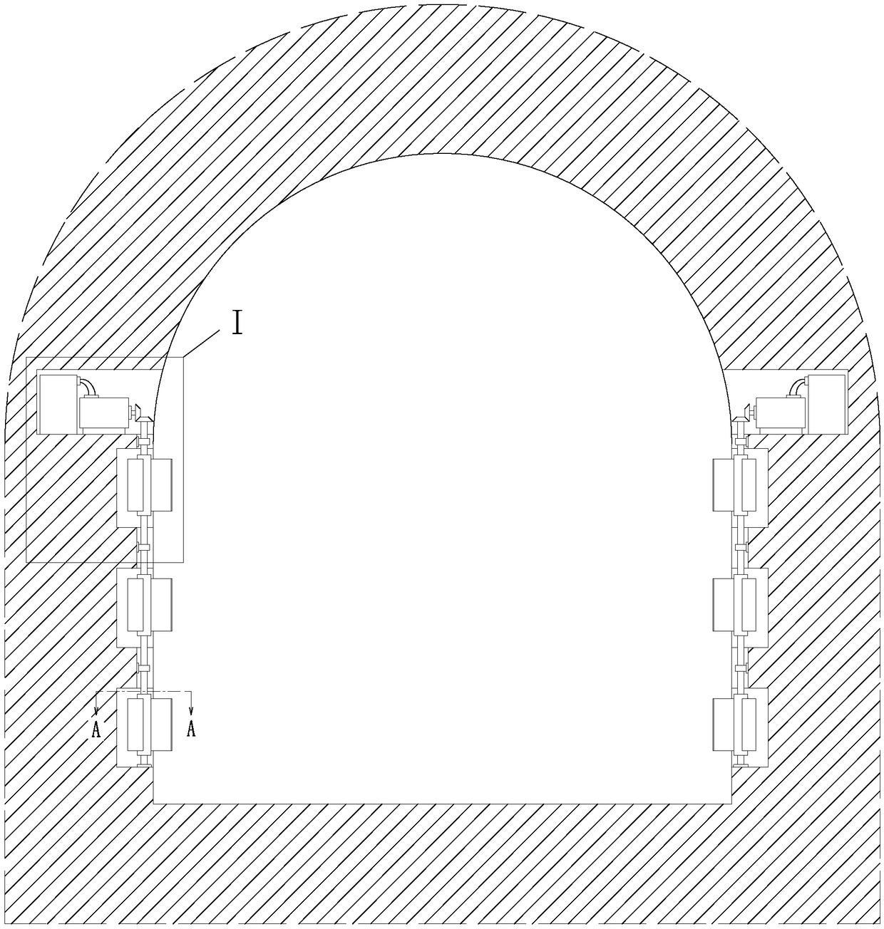
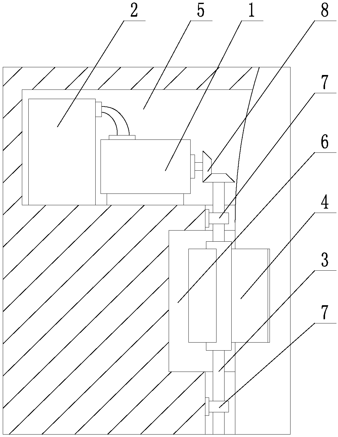
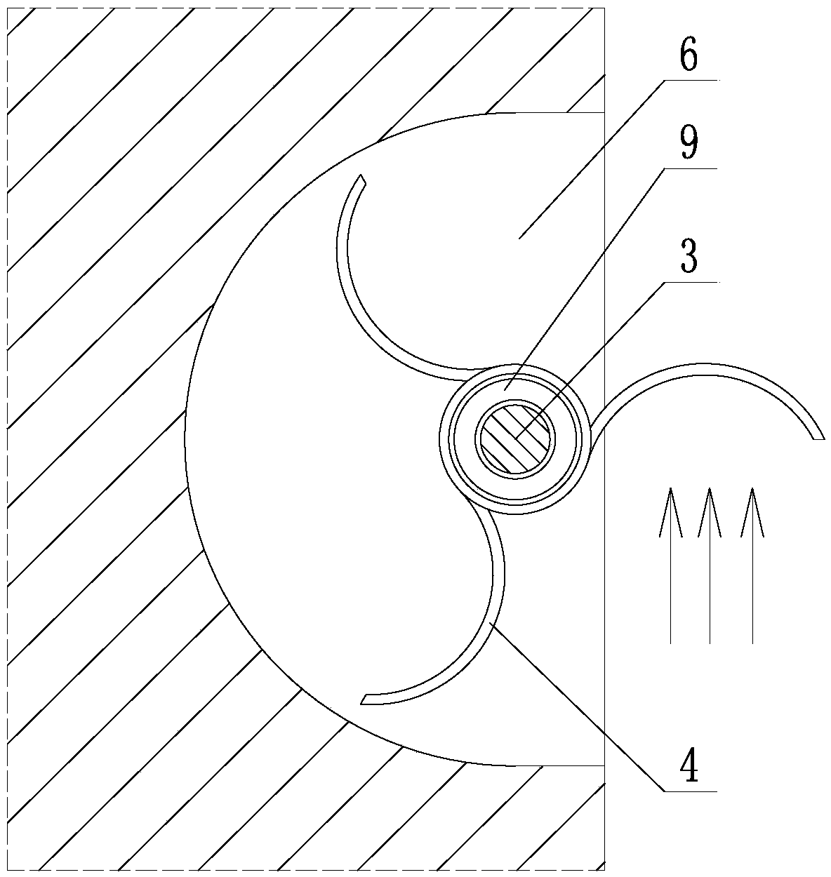
[0014] Such as Figure 1~3 As shown, a subway tunnel wind energy power generation device includes a generator 1, an energy storage system 2, a transmission shaft 3, and an impeller 4. The generator 1 and the energy storage system 2 are both arranged in a slot 5 at the top of the tunnel sidewall, Three tunnel side wall surface slots 6 are provided directly below the top slot 5 of the tunnel side wall, and the three tunnel side wall surface slots 6 are equally spaced in the vertical direction; the transmission shaft 3 passes through the bearing seat 7 Straightly installed on the surface of the side wall of the tunnel, the top end of the drive shaft 3 is connected to the motor shaft of the generator 1 through a bevel gear set 8; Three impellers 4 are installed on the transmission shaft 3, and the three impellers 4 are respectively located in the slots 6 ...


PUM


Abstract

The invention discloses a metro tunnel wind power generation device. The device comprises an electric generator, an energy storage system, a transmission shaft and impellers. The electric generator and the energy storage system are arranged inside a tunnel side wall top groove. Three tunnel side wall surface grooves which are distributed at equal intervals are formed under the tunnel side wall topgroove in the vertical direction. The transmission shaft is vertically mounted on the surface of the side all of a tunnel through a bearing pedestal. The top end of the transmission shaft is connected with a motor shaft of the electric generator through a bevel gear set. The electric generator is connected with the energy storage system, and the energy storage system is used for storing electricenergy generated by the electric generator. The three impellers are mounted on the transmission shaft and located in the three tunnel side wall surface grooves correspondingly. The impellers are connected with the transmission shaft through overrunning couplers, so that the three impellers are made to operate in a coaxial but non-linkage state relative to the transmission shaft and rotate independently on the transmission shaft. Three semi-circular-arc-shaped blades are arranged on each impeller, and the tunnel side wall surface grooves are each in a semi-circular-arc shape. During rotating ofeach impeller, only one blade is located outside the corresponding tunnel side wall surface groove and participates in doing work each time.

Description

technical field [0001] The invention belongs to the technical field of special wind power generation, in particular to a subway tunnel wind power generation device. Background technique [0002] In the subway tunnel, since the moving direction of the subway train is fixed, and the shape of the subway tunnel is also fixed, when the subway train runs at high speed in the tunnel, it will generate a strong directional airflow, and this directional airflow is relatively stable, so it can be For wind power generation. [0003] At present, although many tunnel wind power generation devices have appeared, the actual power generation effect is not ideal. For example, the Chinese patent application number 201220093939.3 discloses a vertical axis wind power generation system using wind energy in subway tunnels. The impeller structure includes Four integral blades with a certain height are used. Since the airflow in the tunnel is not evenly distributed in the vertical space, it cannot ...

Claims


Application Information

Patent Timeline
IPC IPC(8): F03D9/11F03D9/46F03D3/02F03D3/06F03D15/00
CPCF03D3/02F03D3/06F03D9/11F03D9/46F03D15/00Y02B10/30Y02E10/728Y02E10/74Y02E70/30
Inventor 付治国周思宇
Owner LIAONING TECHNICAL UNIVERSITY
Why Eureka
Try Eureka