
A surface miniature piezoelectric power generation device

A piezoelectric power generation and miniature technology, applied in the direction of generators/motors, piezoelectric effect/electrostrictive or magnetostrictive motors, electrical components, etc., can solve the difficulty of collecting, storing and reusing micro-machines, and restrict piezoelectricity The development and application of power generation technology, poor cycle performance and other problems, to achieve the effect of excellent cycle compressibility, good power generation effect, and simple structure

Inactive Publication Date: 2018-12-21
CHENDU NEW KELI CHEM SCI CO LTD
View PDF2 Cites 0 Cited by
  • Summary
  • Abstract
  • Description
  • Claims
  • Application Information

AI Technical Summary

Problems solved by technology

In addition, Chen Wenge and others invented a piezoelectric power generation and energy storage device for road surfaces (China Invention Patent Application No. 201420857671.5), which includes a buffer layer set on the roadbed, and multiple piezoelectric sheets are set on the buffer layer. A plurality of piezoelectric sheets are connected to the energy storage device after being mixed with wires, and an asphalt layer is arranged on the top of the piezoelectric sheet; However, it is difficult to collect, store and reuse; it only needs to carry out simple transformation on urban roads, lay piezoelectric devices in the road surface or directly use piezoelectric materials as road components, and generate electricity through the vibration of the road surface when the vehicle is walking, and Store this energy and use it when necessary
[0006] It can be seen that the piezoelectric power generation devices in the prior art generally have the defects of poor elasticity and low sensitivity, resulting in poor power generation effect and poor cycle performance, which restricts the development and application of piezoelectric power generation technology

Method used


Image

  • A surface miniature piezoelectric power generation device

Examples

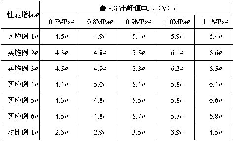

Embodiment 1

[0029] The road micro piezoelectric power generation device is composed of an upper cover, a lower cover, an electromechanical conversion unit, and an air cushion; the electromechanical conversion unit is a metal sheet surrounded by piezoelectric ceramics-polyurethane sponge composite material, and the electromechanical conversion unit is electrically connected to an output end; the air cushion is set under the micro piezoelectric sheet to provide a deformation space for the micro piezoelectric ceramic-polyurethane sponge.

[0030] The preparation process of the piezoelectric ceramic-polyurethane sponge composite material is as follows:

[0031] Add 26kg of nano-potassium sodium metaniobate powder to 71g of water, then add 3kg of sodium methylene bis-naphthalene sulfonate, stir at a high speed of 950r / min, and ultrasonically disperse for 30min at an ultrasonic frequency of 105kHz to obtain nano-piezoelectric Dispersion glue of ceramic powder material; then the polyurethane spo...

Embodiment 2

[0036] The road micro piezoelectric power generation device is composed of an upper cover, a lower cover, an electromechanical conversion unit, and an air cushion; the electromechanical conversion unit is a metal sheet surrounded by piezoelectric ceramics-polyurethane sponge composite material, and the electromechanical conversion unit is electrically connected to an output end; the air cushion is set under the micro piezoelectric sheet to provide a deformation space for the micro piezoelectric ceramic-polyurethane sponge.

[0037] The preparation process of the piezoelectric ceramic-polyurethane sponge composite material is as follows:

[0038] Add 20kg of nano barium strontium metaniobate powder into 78kg of water, then add 2kg of sodium methylene bismethyl naphthalene sulfonate, stir at a high speed of 800r / min, and ultrasonically disperse at an ultrasonic frequency of 80kHz for 50min to obtain nano Dispersion glue of piezoelectric ceramic powder material; then the polyuret...

Embodiment 3

[0041]The road micro piezoelectric power generation device is composed of an upper cover, a lower cover, an electromechanical conversion unit, and an air cushion; the electromechanical conversion unit is a metal sheet surrounded by piezoelectric ceramics-polyurethane sponge composite material, and the electromechanical conversion unit is electrically connected to an output end; the air cushion is set under the micro piezoelectric sheet to provide a deformation space for the micro piezoelectric ceramic-polyurethane sponge.

[0042] The preparation process of the piezoelectric ceramic-polyurethane sponge composite material is as follows:

[0043] Add 30kg of nanometer lead zirconate titanate powder into 66kg of water, then add 4kg of polyethylene glycol, stir at a high speed of 1200r / min, and ultrasonically disperse for 20min at an ultrasonic frequency of 120kHz to obtain nano piezoelectric ceramic powder materials. Disperse the glue; then clean the polyurethane sponge with deio...


PUM


Abstract

The invention belongs to the technical field of power generation devices and provides a pavement miniature piezoelectric power generation device. The pavement micro-piezoelectric power generation device is composed of an upper cover, a lower cover, an electromechanical conversion unit and an air cushion. The electromechanical conversion unit is a metal sheet and is surrounded by a piezoelectric ceramic-Polyurethane sponge composite material. The Piezoelectric ceramic-Polyurethane sponge composite material is prepared by immersing polyurethane sponge in the dispersion of nano-piezoelectric ceramic powder, curing and drying. Compared with the traditional method, the pavement miniature piezoelectric power generation device of the invention utilizes the composite material with high elasticityand high sensitivity prepared by using the polyurethane sponge and the piezoelectric ceramic material, can generate larger strain under the action of smaller compressive stress, has good power generation effect, is simple in structure, is not easy to be damaged, is low in cost, and is suitable for popularization and application.

Description

technical field [0001] The invention belongs to the technical field of power generation devices and provides a road micro piezoelectric power generation device. Background technique [0002] Energy is the key to technological development. The development of major technologies in history is related to the utilization of new energy or the improvement of energy utilization methods. All human activities are inseparable from energy, and the development of society is based on energy consumption. With the depletion of environmental resources, the recovery and reuse of energy has been valued by the whole society. In recent years, the road mileage and the number of motor vehicles in my country have increased rapidly, and a large amount of mechanical vibration energy has been accumulated inside the road under the frequent action of vehicle loads. Therefore, the development of a power generation surface that can convert the mechanical strain energy inside the road into electrical en...

Claims


Application Information

Patent Timeline
IPC IPC(8): H02N2/18C08J9/40C08L75/04
CPCH02N2/186C08J9/40C08J2375/04C08L75/04
Inventor 陈庆司文彬
Owner CHENDU NEW KELI CHEM SCI CO LTD
Learn More