
Polytetrafluoroethylene compensator and manufacturing technology thereof

A technology of polytetrafluoroethylene and manufacturing process, which is applied in the field of compensators, can solve the problems of affecting product quality, wasting resources, and uneven waveforms of compensators, so as to improve the volume resistance value, prolong the service life, and avoid the phenomenon of micropores Effect

Pending Publication Date: 2018-10-12
NANJING FUYUAN CHEM PIPELINE EQUIP
View PDF10 Cites 0 Cited by
  • Summary
  • Abstract
  • Description
  • Claims
  • Application Information

AI Technical Summary

Problems solved by technology

[0006] 1. The PTFE compensator formed by hot calendering has local tensile deformation, and the micropores between the pipes or plates will become larger during the drawing process, and serious leakage will occur;
[0007] 2. The waveform of the compensator formed by hot rolling is not uniform and difficult to shape. The compensator made by the same mold or the same person will be quite different, and the shape will be restored under the condition of temperature;
[0008] 3. The service life of the PTFE compensator formed by hot rolling is generally short due to the existence of the above (1) and (2);
[0009] 4. The PTFE compensator produced by lathing thick-walled PTFE molded tubes uses a lot of materials and cannot be processed too long. If it is too long, it will be difficult to control the processing accuracy because the workpiece starts to soften, which will affect the product quality. In addition, the processed ones PTFE waste is difficult to recycle and can only be treated as waste, wasting resources

Method used


Image

  • Polytetrafluoroethylene compensator and manufacturing technology thereof
  • Polytetrafluoroethylene compensator and manufacturing technology thereof
  • Polytetrafluoroethylene compensator and manufacturing technology thereof

Examples


Embodiment Construction

[0048] In order to make the technical solutions of the present invention clearer and clearer to those skilled in the art, the present invention will be further described in detail below in conjunction with the examples and accompanying drawings, but the embodiments of the present invention are not limited thereto.

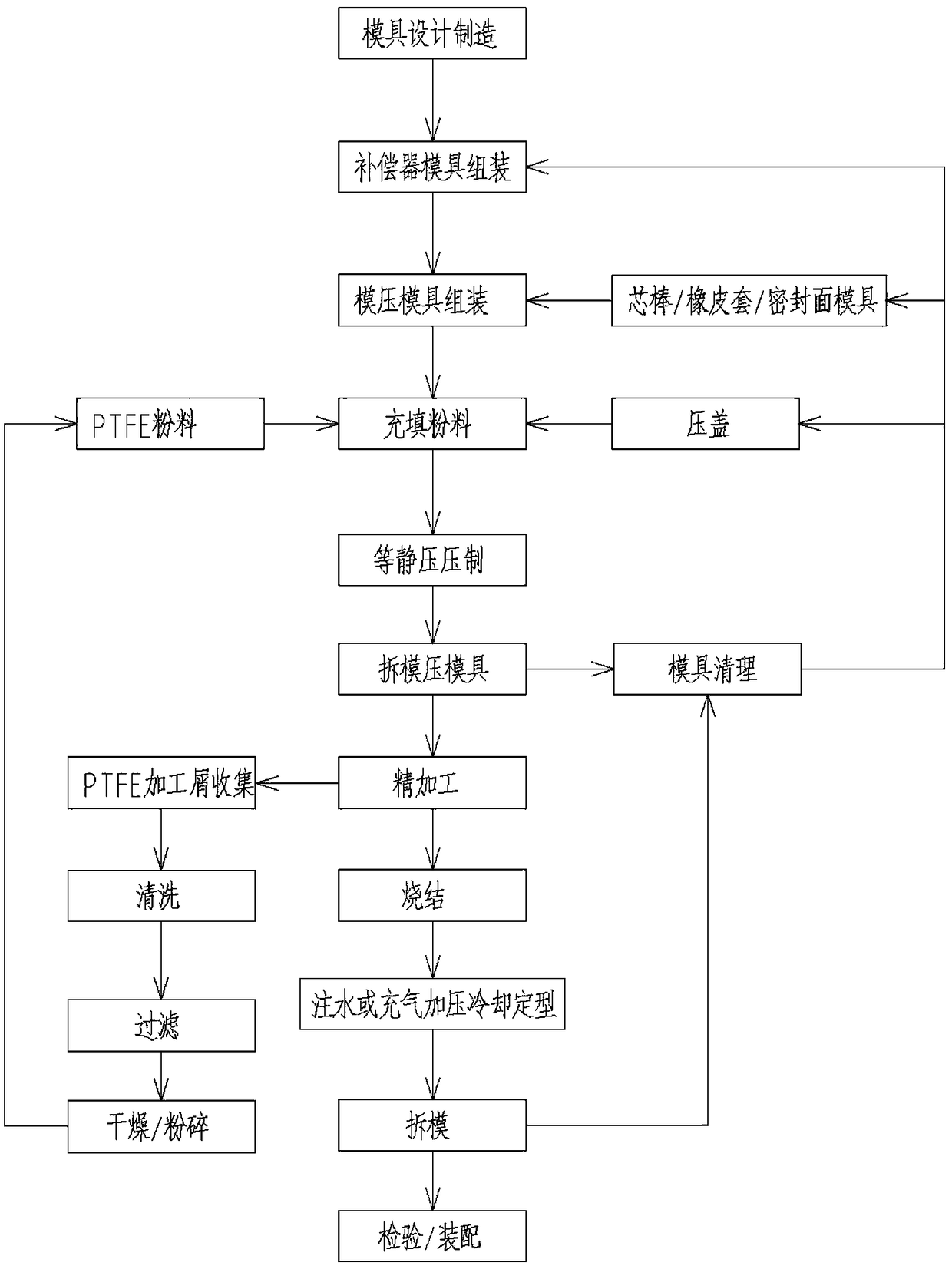
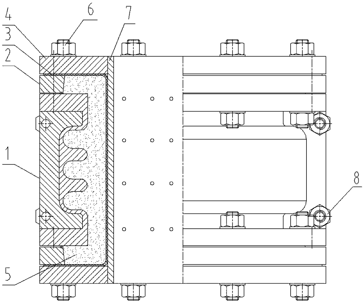
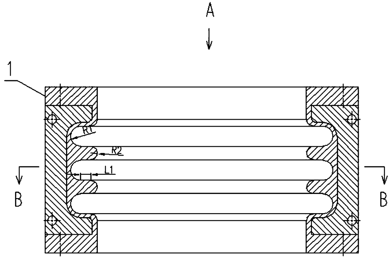
[0049] Such as Figure 2-Figure 9 As shown, the polytetrafluoroethylene compensator provided in this embodiment includes a compensator mold 1 and a tetrafluoroethylene compensator 9, each sealing surface of the compensator mold 1 is provided with a sealing surface mold 2, and one side of the compensator mold 1 There is a molded mandrel 7, a rubber sleeve 3 is provided between the compensator mold 1 and the molded mandrel 7, a sealing compression flange 4 is installed on the compensator mold 1, and a fastener is provided on the sealing compression flange 4 6. The cavity between the sealing surface mold 2, the compensator mold 1 and the rubber sleeve 3 is filled with...


PUM


Abstract

The invention discloses a polytetrafluoroethylene compensator and a manufacturing technology thereof, and belongs to the technical field of compensators. The polytetrafluoroethylene compensator comprises a compensator die and a tetrafluorohydrazine compensator, wherein a sealing surface die is arranged on each sealing surface of the compensator die; a die pressing mandrel is arranged at one side of the compensator die; a rubber sleeve is arranged between the compensator die and the die pressing mandrel; a sealing compressing flange is mounted on the compensator die; a fastener is arranged on the sealing compressing flange; empty cavities among the sealing surface die, the compensator die and the rubber sleeve are filled with PTFE (polytetrafluoroethylene) powder; and the compensator die isof a single-wave or multi-wave form and is manufactured through a stainless steel material. The polytetrafluoroethylene compensator is simple in structure, and convenient to use, and can be insertedand formed in one time; the size is uniform; in addition, wave form is fixed, so that the thermal deformation is avoided; standardization is easily realized; local stretching deformation is avoided; micropores are avoided. Therefore, the service life is greatly prolonged; and meanwhile, waste materials are not produced in the whole circulating process, so that the energy saving and consumption reducing effects can be achieved.

Description

technical field [0001] The invention relates to a compensator and a manufacturing process thereof, in particular to a polytetrafluoroethylene compensator and a manufacturing process thereof, and belongs to the technical field of compensators. Background technique [0002] PTFE compensators are widely used in chemical and pharmaceutical anti-corrosion pipelines, and there are corresponding national standards and industry standards. Now the production process of PTFE compensators is mainly as follows: [0003] 1. Compensator for normal pressure or micro-negative pressure conditions: Manufactured by winding PTFE tubes, dispersed material PTFE tubes or welded PTFE tubes by calendering, pressure and heating. [0004] 2. PTFE compensator used in high vacuum working conditions: Manufactured by turning thick-walled PTFE molded tubes. [0005] Defects and deficiencies of the prior art: [0006] 1. The PTFE compensator formed by hot calendering has local tensile deformation, and the...

Claims


Application Information

Patent Timeline
Patent Type & Authority Applications(China)
IPC IPC(8): F16L51/02B29C69/02B29C43/10B29C67/04B29K27/18
CPCF16L51/025B29C43/003B29C43/006B29C43/104B29C2043/106B29K2027/18
Inventor 王纯星陆福洲曹雷李水林经亮亮吴北京
Owner NANJING FUYUAN CHEM PIPELINE EQUIP
Learn More