Quick ionized water structure

A technology of ionic water and casing, applied in water heaters, fluid heaters, household appliances, etc., can solve the problems of low conversion rate, achieve the effects of improving heating efficiency, increasing water inflow time, and increasing head

Pending Publication Date: 2018-10-12
SHENZHEN DAOGE SCI & TECH CORP LTD
View PDF8 Cites 0 Cited by
  • Summary
  • Abstract
  • Description
  • Claims
  • Application Information

AI Technical Summary

Problems solved by technology

However, its condensing device and evaporating device (copper tube) are wound on the circulating water pipe to achieve the purpose of heat exchange, and the conversion rate of this heat exchange method is low

Method used


Image

  • Quick ionized water structure

Examples


Embodiment Construction

[0016] The embodiments of the present invention will be described in detail below with reference to the accompanying drawings, but the present invention can be implemented in many different ways defined and covered by the claims.

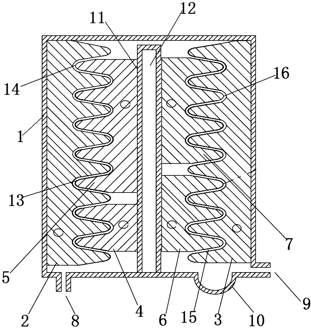
[0017] like figure 1 As shown, a fast ionized water structure includes a housing 1, and the housing 1 is provided with a central partition 11, a first L pole transducing block 4, a second L pole transducing block 5, and a third L pole transducing block block 6, the fourth L-pole transducing block 7, the first N-pole transducing block 2 and the second N-pole transducing block 3, the central partition 11 is arranged in the middle position inside the housing 1, and the first The N pole transducing block 2 is connected to the inner wall of the left side of the housing 1, the second N pole transducing block 3 is connected to the right side inner wall of the housing 1, and the first L pole transducing block 4 is connected to the The lower left side of th...


PUM


Abstract

The invention discloses a quick ionized water structure. A central partition is arranged in the middle of the interior of a housing; a first N-pole energy conversion block is connected to the inner wall of a left side edge of the housing; a second N-pole energy conversion block is connected to the inner wall of a right side edge of the housing; a first L-pole energy conversion block is connected to a lower left edge of the central partition; a second L-pole energy conversion block is connected to an upper left edge of the central partition; a third L-pole energy conversion block is connected to a lower right edge of the central partition; and a fourth L-pole energy conversion block is connected to an upper right edge of the central partition. The quick ionized water structure has the following beneficial effects: the plurality of energy conversion blocks are arranged to improve the energy conversion effect; clearance grooves are formed between the energy conversion blocks; water flowsinto gaps; as a first clearance groove, a second clearance groove and a third clearance groove are wavy, the lift of the clearance grooves is increased, the water inflow time is prolonged, and the heating efficiency is improved; and the quick ionized water structure is simple, safe and reliable.

Description

technical field [0001] The invention relates to the technical field of heat exchange, in particular to a fast ionized water structure. Background technique [0002] Chinese Patent Document No. CN201079320 disclosed a jacuzzi on July 2, 2008, especially a jacuzzi whose temperature can be adjusted. It includes a cylinder body and a water pipe. A copper pipe is wound on the outside of the water pipe. One end of the copper pipe is connected to a capillary, and the other end is connected to a compressor; the capillary and the compressor are respectively connected to a condensing device. It is said that it can realize both hot water heating and cooling water; the energy consumption is lower than that of electric heating wire (heating). However, its condensing device and evaporating device (copper pipe) are wound on the circulating water pipe to achieve the purpose of heat exchange, and the conversion rate of this heat exchange method is relatively low. Therefore, further improve...

Claims


Application Information

Patent Timeline
Patent Type & Authority Applications(China)
IPC IPC(8): F24H1/10F24H9/18F25D31/00
CPCF24H1/10F24H9/1809F25D31/002F25D31/005
Inventor 樊劲松林国华
Owner SHENZHEN DAOGE SCI & TECH CORP LTD
Why Eureka
Try Eureka