Method for achieving tractor shearing stress sensing by using magnetic induction

A technology of shear stress and tractor, which is applied in the measurement of the change force of the material magnetic properties caused by the applied stress, force/torque/power measuring instrument, measuring device, etc., can solve the problem of lack of tractor resistance detection method, etc., to achieve Sensitive and precisely controlled effects

Inactive Publication Date: 2018-10-12
SOUTHWEST UNIVERSITY
View PDF5 Cites 6 Cited by
  • Summary
  • Abstract
  • Description
  • Claims
  • Application Information

AI Technical Summary

Problems solved by technology

[0003] However, the most important problem in the setting of the electro-hydraulic suspension system at present is how to establish the mechanical displacement and the conversion of the tractor resistance to the electrical signal. The electro-hydraulic suspension system is more sensitive and precise to achieve control. Therefore, those skilled in the art are committed to developing a method of using magnetic induction to realize tractor shear stress sensing, which can accurately sense the tractor’s resistance and realize it in the resistance control system more accurately. Feedback, so that the electro-hydraulic suspension system is more sensitive and precise to achieve control

Method used


Image

  • Method for achieving tractor shearing stress sensing by using magnetic induction
  • Method for achieving tractor shearing stress sensing by using magnetic induction
  • Method for achieving tractor shearing stress sensing by using magnetic induction

Examples


Embodiment Construction

[0039] Below in conjunction with accompanying drawing and embodiment the present invention will be further described:

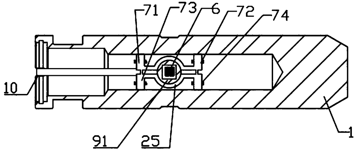
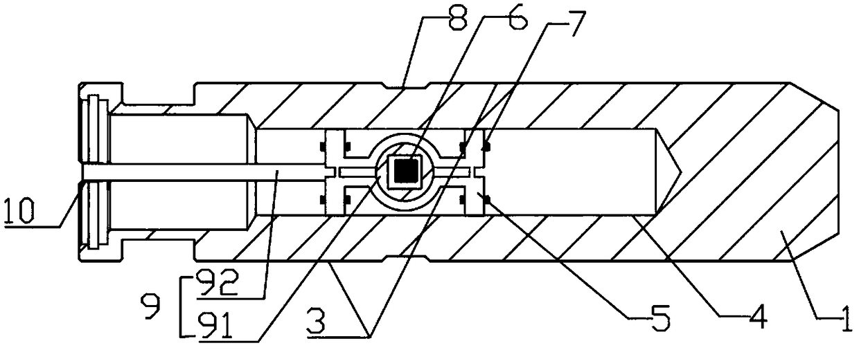
[0040] Such as figure 1 Shown, a kind of method utilizing magnetic induction to realize tractor shear stress sensing is characterized in that: comprise the following steps:

[0041] 1) The excitation core 6 is set so that the magnetic field lines of the excitation core are fixed perpendicular to the paper surface and diverge outward;

[0042] 2) On the left and right sides of the exciting magnetic core 6, the first to fourth induction magnetic cores whose induction surfaces are parallel to the paper surface are arranged respectively, so that the longitudinal section where the magnetic pole of the excitation magnetic core is located is 90° to the longitudinal section where the magnetic pole of the induction magnetic core is located; An induction core 71 and a second induction core 72 are arranged symmetrically along the excitation core 6; a third induction co...


PUM


Abstract

The invention discloses a method for achieving tractor shearing stress sensing by using magnetic induction. The method comprises the following steps that (1) an excitation magnetic core is arranged sothat a magnetic induction line of the excitation magnetic core is fixedly perpendicular to a paper surface and diverges outwards; (2) the left and right edges of the excitation magnetic core are respectively provided with a first induction magnetic core,a second induction magnetic core,a third induction magnetic core and a fourth induction magnetic core of which the induction surfaces are parallel to a paper surface so that an included angle between the longitudinal profile where the a magnetic pole of the excitation magnetic core is located and the longitudinal profile where magnetic poles of the induction magnetic cores are located is 90 degrees; (3) induction coils with the same number of turns wind the first induction magnetic core,the second induction magnetic core,the third induction magnetic core and the fourth induction magnetic core respectively; and (4) the first induction magnetic core,the second induction magnetic core,the third induction magnetic core,the fourth inductionmagnetic core and the excitation magnetic core are placed on a shearing stress induction area so that the side surfaces of the first induction magnetic core,second induction magnetic core,third induction magnetic core and fourth induction magnetic core can receive induction forces. The method for achieving the tractor shearing stress sensing by using the magnetic induction has the advantages thatthe shearing stress detection during the tractor operation can be can precisely achieved so that the resistance suffered by the tractor can be precisely induced.

Description

technical field [0001] The invention relates to the field of agricultural machinery, in particular to a method for realizing tractor shear stress sensing by using magnetic induction. Background technique [0002] In order to adapt to various farm implements and their different operating conditions, most wheeled tractors currently generally adopt three adjustment methods: force adjustment, position adjustment, and height adjustment. In recent years, foreign tractors have also adopted torque adjustment, pressure adjustment, Comprehensive regulation. The force adjustment is to maintain the tractor engine load stability, and is used to adjust the traction force of the farm implements. It is realized through the resistance control system. The resistance control system is a very important subsystem of the electro-hydraulic suspension system. Traditional tractors use a simple hydraulic device as the driving force for farm implements, and the control part is mechanical. The driver ...

Claims


Application Information

Patent Timeline
Patent Type & Authority Applications(China)
IPC IPC(8): G01L5/00G01L1/12
Inventor 李明生叶进杨仕柳剑曾百功
Owner SOUTHWEST UNIVERSITY
Why Eureka
Try Eureka