High-voltage test clamping jaw device and test system

A high-voltage test and gripper technology, which is applied in the direction of measuring devices, measuring device casings, and measuring electrical variables, can solve problems such as difficult to meet high-voltage and high-current energization tests, and achieve the effects of small impedance, large conductive area, and long life.

Pending Publication Date: 2018-10-12
SHANGHAI JINDONGTANG TECH CO LTD
View PDF0 Cites 2 Cited by
  • Summary
  • Abstract
  • Description
  • Claims
  • Application Information

AI Technical Summary

Problems solved by technology

[0004] The purpose of the present invention is to provide a high-voltage test jaw device to solve the technical problem

Method used


Image

  • High-voltage test clamping jaw device and test system
  • High-voltage test clamping jaw device and test system
  • High-voltage test clamping jaw device and test system

Examples


Example Embodiment

[0043] The technical solutions of the present invention will be clearly and completely described below in conjunction with the accompanying drawings. Apparently, the described embodiments are some of the embodiments of the present invention, but not all of them. Based on the embodiments of the present invention, all other embodiments obtained by persons of ordinary skill in the art without making creative efforts belong to the protection scope of the present invention.

[0044] In the description of the present invention, it should be noted that the terms "center", "upper", "lower", "left", "right", "vertical", "horizontal", "inner", "outer" etc. The indicated orientation or positional relationship is based on the orientation or positional relationship shown in the drawings, and is only for the convenience of describing the present invention and simplifying the description, rather than indicating or implying that the referred device or element must have a specific orientation, ...


PUM


Abstract

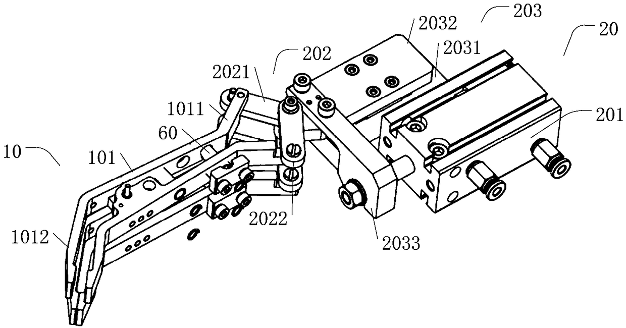
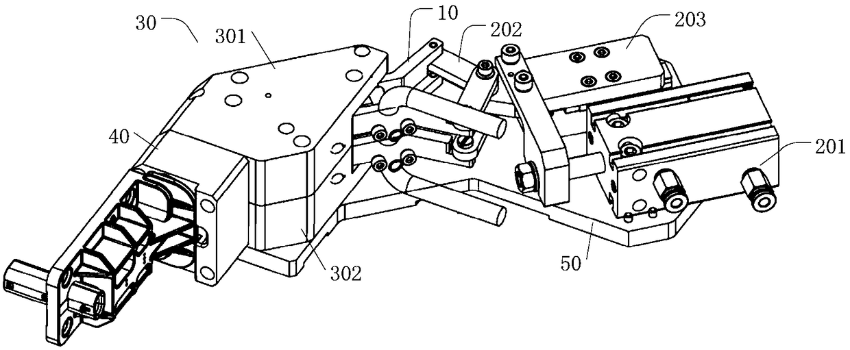
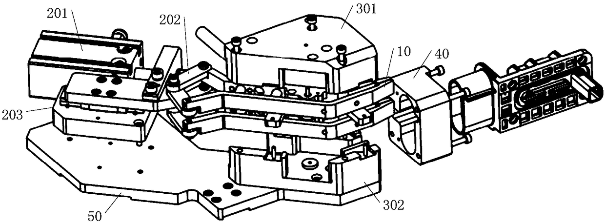
The present invention relates to a high-voltage test clamping jaw device and a test system. The high-voltage test clamping jaw device comprises a clamp set, the clamp set comprises two clamping portion oppositely arranged in a horizontal direction; each clamping portion comprises a clamping end and a drive end which are oppositely arranged in a length direction of the clamping portion, and the twoclamping portions are hinged at the middle area; the drive mechanisms are connected with the two drive ends of the clamping portions at the same time to drive the two clamping end to be far away fromeach other through the two drive ends to allow products to be tested to enter between the two clamping ends or to be close to each other to allow the products to be tested to be clamped between the two clamping ends.

Description

technical field [0001] The invention relates to the technical field of voltage testing, in particular to a high-voltage testing jaw device and a testing system. Background technique [0002] Traditional voltage and current tests generally use contact tests, such as contact tests using probes or small shrapnel. [0003] Generally, the probe or small shrapnel can test the current of 1A-10A, its conductive area is small, the contact area is small, and the impedance is large. When it is applied to high voltage and high current energization test, the probe and small shrapnel heat up quickly, have short life and are safe. The resistance is low, and the surface of the product to be tested is easily damaged. Contents of the invention [0004] The purpose of the present invention is to provide a high-voltage test jaw device to solve the technical problem that the traditional voltage and current test device is difficult to meet the high-voltage and high-current energization test. ...

Claims


Application Information

Patent Timeline
IPC IPC(8): G01R1/04G01R19/00
CPCG01R1/0425G01R19/00
Inventor 黎子龙郜亮
Owner SHANGHAI JINDONGTANG TECH CO LTD
Why Eureka
Try Eureka