
Spatial microphone positioning method based on sound source array

A sound source array and positioning method technology, applied in positioning, measuring devices, instruments, etc., can solve the problems of inconvenient installation, inability to realize online estimation of microphone position, and inability to realize spatial distribution of microphone position estimation, etc.

Active Publication Date: 2018-10-12
HEBEI UNIV OF TECH
View PDF9 Cites 9 Cited by
  • Summary
  • Abstract
  • Description
  • Claims
  • Application Information

AI Technical Summary

Problems solved by technology

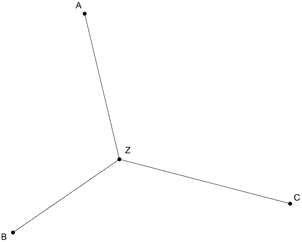
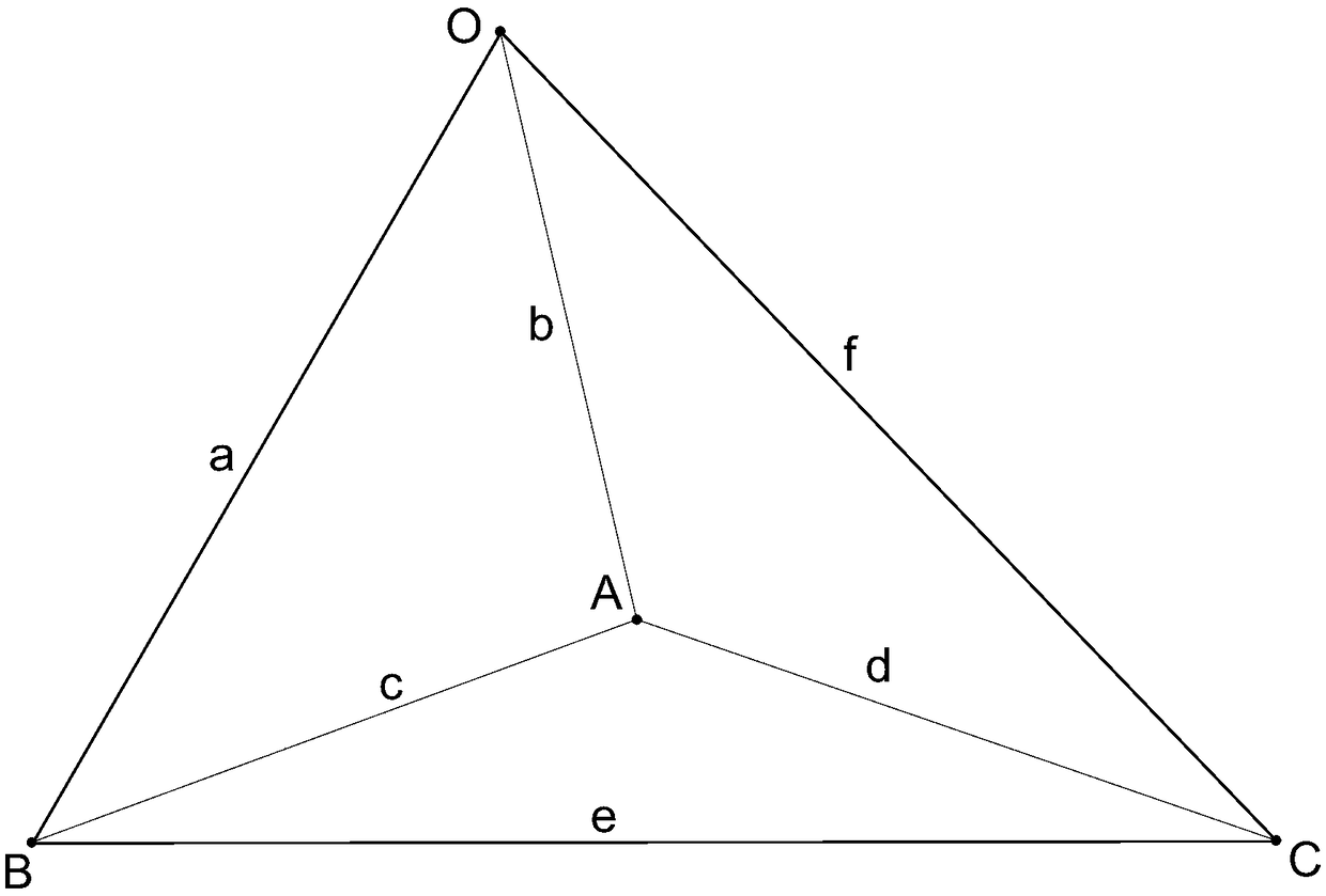
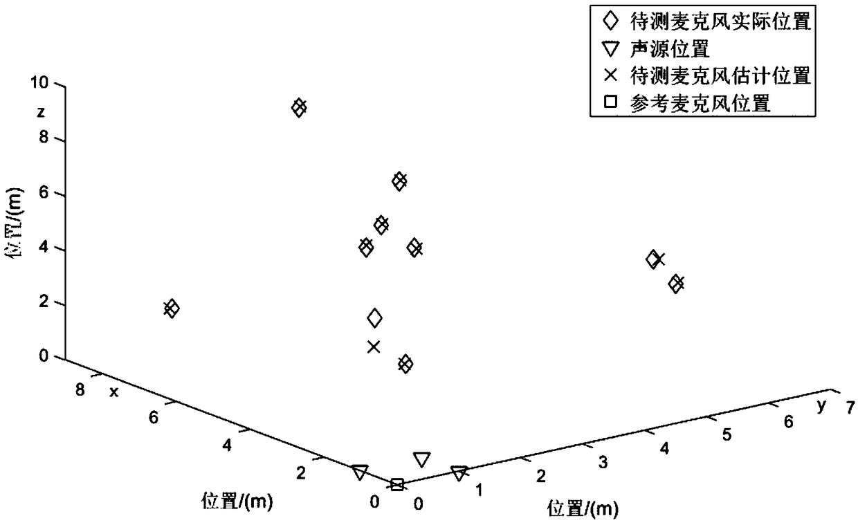
[0005] The technical problem to be solved by the present invention is: a method for locating a spatial microphone based on a sound source array. The sound signal of the frequency band is used as the sound signal of the three sound sources to realize the spatial estimation of the microphone position. The sound signals of the three different frequency bands are received by the microphone to be located and the reference microphone, and the distance between the microphone to be located and the sound source is calculated. , calculate the spatial position of the microphone to be positioned, and realize the spatial microphone positioning based on the sound source array by means of the sound arrival time difference and the geometric volume solution; It can only be calculated offline, and cannot realize the online estimation of the microphone position and the defect that the position estimation of the spatially distributed microphones cannot be realized

Method used


Image

  • Spatial microphone positioning method based on sound source array
  • Spatial microphone positioning method based on sound source array
  • Spatial microphone positioning method based on sound source array

Examples


Embodiment

[0041] In this embodiment, a spatial microphone positioning method based on a sound source array, the specific steps are as follows:

[0042] The first step is to set up the equipment used in the spatial microphone localization method based on the sound source array:

[0043] In a three-dimensional space, set the equipment used in the spatial microphone localization method based on the sound source array, including a sound source distribution unit, a reference microphone, a microphone to be positioned, and a microphone signal processing unit; wherein, the above sound source distribution unit consists of three sound source distribution units. The sources are arranged in a triangle and are fixed in a triangle. These three sound sources are sound source 1 with space coordinates S1(x1,y1,z1), sound source 2 with space coordinates S2(x2,y2,z2) and space The coordinates are the sound source 3 of S3(x3, y3, z3), and the three sound sources simultaneously emit three sound signals with...


PUM


Abstract

The invention provides a spatial microphone positioning method based on a sound source array and relates to the field of indoor positioning. According to the method, a device composed of a sound source distribution unit, a reference microphone, a to-be-positioned microphone and a microphone signal processing unit is used, three sound signals different in frequency band are selected and used as sound production signals of three sound sources to achieve spatial estimation of the microphone position, and the three sound signals different in frequency band are received by the to-be-positioned microphone and the reference microphone; by calculating the distance between the to-be-positioned microphone and the sound sources, the spatial position of the to-be-positioned microphone is calculated; through a mode of sodar time difference and geometric volume solution, spatial microphone positioning based on the sound source array is achieved. The defects in the prior art are overcome that the operation is cumbersome, the efficiency is low, installation is inconvenient, only offline calculation can be conducted, and online estimation of the microphone position and position estimation of the spatially distributed microphones cannot be achieved.

Description

technical field [0001] The technical solution of the present invention relates to the field of indoor positioning, in particular to a spatial microphone positioning method based on a sound source array. Background technique [0002] With the continuous development of sensor technology, in the application of service robot products, it is often necessary to obtain the location of spatial landmarks for the navigation of robot products. Compared with the traditional perception methods of lidar and vision, the auditory method is used to process the sound signal, and the robot auditory system constructed from the perspective of humanoid has become an important research object in the field of robotics. Compared with other sensing methods, the sound method can make up for the visual sensing method's inability to extract feature points in large open areas and its heavy dependence on light. [0003] In the existing technologies, sound source localization methods based on microphone a...

Claims


Application Information

Patent Timeline
IPC IPC(8): G01S5/26
CPCG01S5/26
Inventor 杨鹏翟葆朔孙昊陈晓辉王硕朋
Owner HEBEI UNIV OF TECH
Learn More