

Long-focus lens
A telephoto lens and lens technology, applied in the field of telephoto lenses, can solve the problems of large magnification, small depth of field, etc., and achieve the effect of large magnification, small depth of field, and good aberration correction
- Summary
- Abstract
- Description
- Claims
- Application Information
AI Technical Summary
Problems solved by technology
Method used
Image

Examples
Embodiment 1
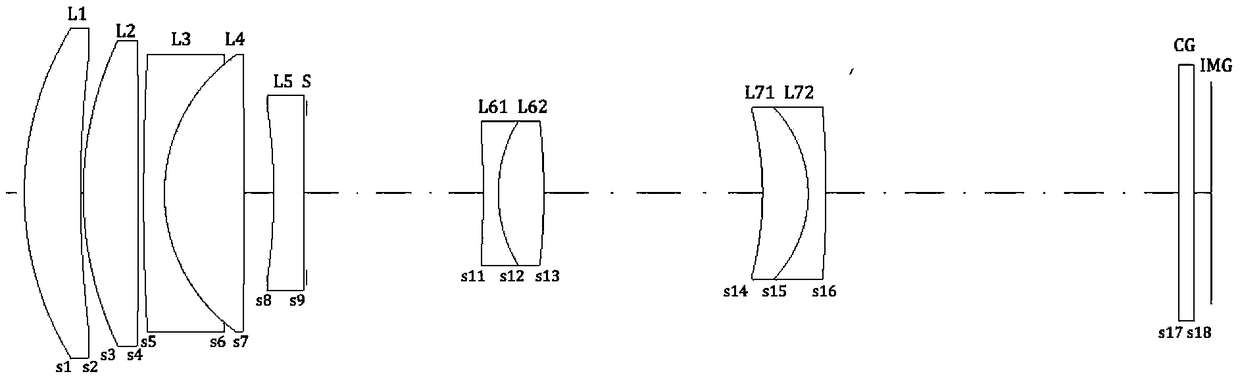
[0034] Such as Figure 1 to Figure 3 As shown, the present embodiment discloses a 70mm telephoto lens, which sequentially includes from the object side to the image side along the optical axis direction: a first lens group, a diaphragm S, a second lens group, a protective glass CG and an image surface img.
[0035] In the first lens group: the first lens L1 is a lunar convex spherical lens, including a first spherical surface s1 (convex surface) and a second spherical surface s2 (concave surface); the second lens L2 is a biconvex spherical lens, including a third spherical surface s3 (convex surface) and the fourth spherical surface s4 (convex surface); the third lens L3 is a lunar convex spherical lens, including the fifth spherical surface s5 (convex surface) and the sixth spherical surface s6 (concave surface); the fourth lens L4 is a biconvex spherical lens, Including the sixth spherical surface s6 (convex surface) and the seventh spherical surface s7 (concave surface); t...
Embodiment 2
[0048] Such as Figure 4 to Figure 6 As shown, compared with Embodiment 1, the third lens L3 of this embodiment is a biconcave spherical lens, including a fifth spherical surface s5 (concave surface) and a sixth spherical surface s6 (concave surface).
[0049] The second lens group in this embodiment includes: sixth lens L6, cemented lens L71, L72, wherein: the sixth lens is a biconcave aspherical lens, including the eleventh aspheric surface s11 (concave surface) and the twelfth aspheric surface The spherical surface s12 (concave surface); the cemented lens L7 is a lunar convex spherical lens, including a fourteenth spherical surface s14 (concave surface) and a sixteenth spherical surface (convex surface) s16.
[0050] The specific parameters of the lens in this embodiment are as follows
[0051] Table 2:
[0052]
[0053]
[0054] In this embodiment, the sixth lens L6 adopts a plastic aspheric surface, wherein: the coefficient of the aspheric surface satisfies:
[0...
Embodiment 3
[0063] Such as Figure 7 to Figure 9 As shown, compared with Embodiment 2, the second lens of this embodiment is a biconvex spherical lens, including the third spherical surface s3 (convex surface) and the fourth spherical surface s4 (concave surface); the fifth lens is a biconcave spherical lens, including Eighth spherical surface s8 (concave surface) and ninth spherical surface s9 (concave surface).
[0064] The second lens group in the present embodiment includes: the sixth lens L6, the seventh lens L7 and the eighth lens L8, wherein: the sixth lens is a biconcave aspheric lens, including the eleventh aspheric surface s11 (concave surface) and The twelfth aspherical surface s12 (concave surface); the seventh lens L7 is a biconcave spherical lens, including the fourteenth spherical surface s13 (concave surface) and the fourteenth spherical surface s14 (concave surface); the eighth lens L8 is a biconvex spherical lens, including Fourteenth spherical surface s15 (convex surfa...
PUM
| Property | Measurement | Unit |
|---|---|---|
| refractive index | aaaaa | aaaaa |
| refractive index | aaaaa | aaaaa |
| Abbe number | aaaaa | aaaaa |
Abstract
Description
Claims
Application Information