Computer liquid cooling source heat dissipation control module

A control module and computer technology, applied in calculation, instrumentation, electrical digital data processing, etc., can solve the problem of unsatisfactory release control of liquid cooling source

Pending Publication Date: 2018-10-12
马思源
View PDF0 Cites 1 Cited by
  • Summary
  • Abstract
  • Description
  • Claims
  • Application Information

AI Technical Summary

Problems solved by technology

However, in the current existing liquid cooling system, the release control of the liquid cooling source is still not ideal, so a set of liquid cooling source heat dissipation control module is needed

Method used


Image

  • Computer liquid cooling source heat dissipation control module
  • Computer liquid cooling source heat dissipation control module
  • Computer liquid cooling source heat dissipation control module

Examples


Embodiment

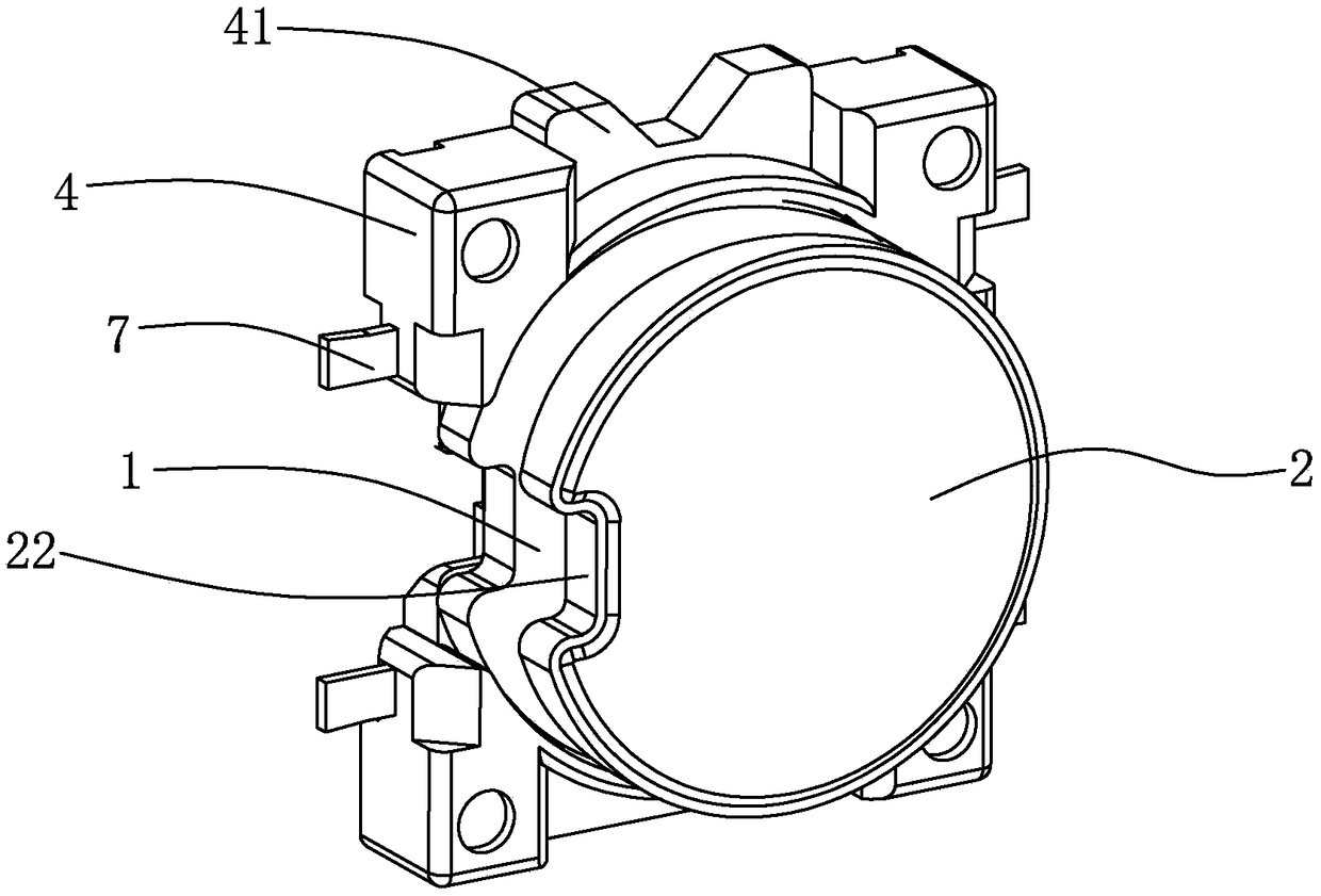
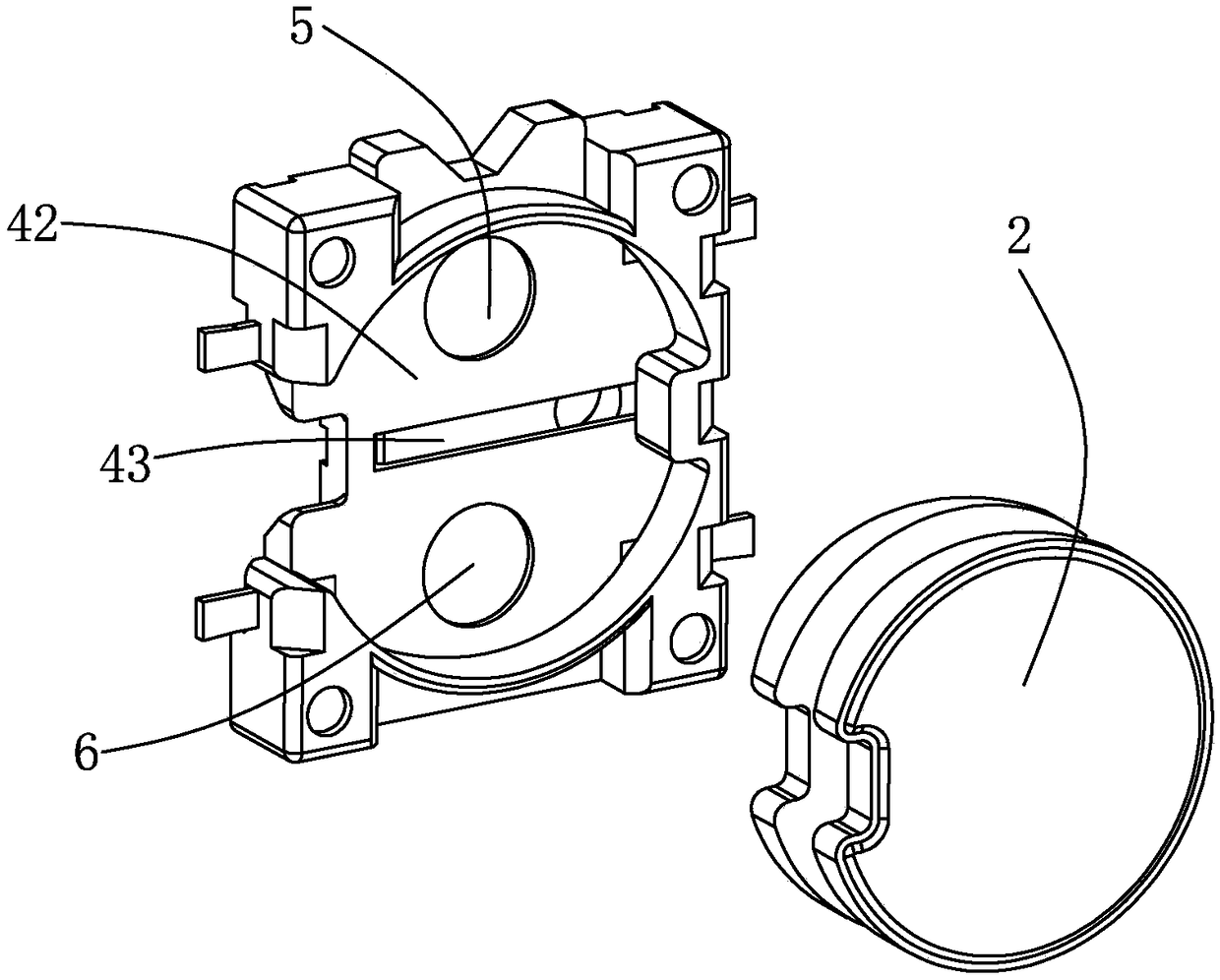
[0023] Embodiment: A heat dissipation control module of a computer liquid cooling source, its main structure includes: valve bottom plate 1, valve top plate 2, iron disc 21, pipe fittings passing through groove 22, air bag column 3, valve base 4, base card slot 41, Valve plate cavity 42, cavity cavity 43, electromagnetic ring a5, electromagnetic ring b6, electrode terminal 7, liquid cooling tube 8, the outer bottom end of the valve base 4 is fixed with a base card slot 41, the valve base 4 is provided with a valve plate inner cavity 42, and the center position of the valve plate inner cavity 42 is provided with a cavity 43, and the left and right sides of the cavity 43 are respectively provided with an electromagnetic ring a5 and an electromagnetic ring b6; a5 and electromagnetic ring b6 are respectively connected to the electrode terminals 7;

[0024] The center position between the valve bottom plate 1 and the valve top plate 2 is clamped and fixed with an airbag column 3, a...


PUM

PropertyMeasurementUnit
Diameteraaaaaaaaaa

Abstract

The invention relates to a computer liquid cooling source heat dissipation control module. A base clamp slot is fixed at one end of a bottom of an outer side of a valve base. A valve plate inner cavity is set in the valve base. An intra-cavity slot is set at the center position of the valve plate inner cavity. An electromagnetic ring a and an electromagnetic b are set at left and right sides of the intra-cavity slot. The electromagnetic ring a and the electromagnetic b are connected with electrode wiring terminals. An air bag column is clamped and fixed at the central position between a valvebottom plate and a valve top plate. An iron sheet disk is placed in the valve top plate. According to the module, a direct current voltage range input by the electromagnetic ring a and the electromagnetic b is 3.6-12V. Input voltages can be linearly adjusted and controlled in real time. When the direct current voltages input by the electromagnetic ring a and the electromagnetic b are peak values,the space between the valve bottom plate and the valve top plate is the limit lowest space. The computer liquid cooling source heat dissipation control module is prepared.

Description

technical field [0001] The invention relates to a heat dissipation control module of a computer liquid cooling source. Background technique [0002] In today's personal computer heat dissipation field, although air-cooled radiators have basically escaped the vicious circle of high-noise and violent heat dissipation, they are generally developing in the direction of large volume, multiple heat pipes, and overweight. It has brought great inconvenience to installation and installation, and it has also brought a great test to the load-bearing and pressure-bearing capacity of computer accessories. In view of the above-mentioned difficulties in the post-air cooling era, liquid cooling radiators have gradually been accepted by the majority of computer users. As a mature heat dissipation technology, liquid cooling has been widely used in industrial methods, such as the heat dissipation of automobiles and aircraft engines. The application of liquid cooling technology to the compute...

Claims


Application Information

Patent Timeline
IPC IPC(8): G06F1/20
CPCG06F1/20G06F2200/201
Inventor 马思源
Owner 马思源
Why Eureka
Try Eureka