
Flue-external wall temperature difference energy collecting device

An energy harvesting and flue technology, applied in the direction of electrical components, generators/motors, etc., can solve the problem of not being able to play all-weather functions, and achieve the effect of lasting and environmentally friendly power supply, avoiding pollution, and avoiding use.

Pending Publication Date: 2018-10-12
ZHEJIANG SCI-TECH UNIV
View PDF9 Cites 0 Cited by
  • Summary
  • Abstract
  • Description
  • Claims
  • Application Information

AI Technical Summary

Problems solved by technology

[0010] In order to overcome the shortcomings of the existing wireless sensor network of intelligent buildings that provide reliable energy due to the limitation of location and time period, and cannot exert all-weather effects, the present invention provides a convenient, durable and environmentally friendly solution for wireless sensor network Powered Flue-External Wall Temperature Difference Energy Harvesting Device

Method used


Image

  • Flue-external wall temperature difference energy collecting device
  • Flue-external wall temperature difference energy collecting device
  • Flue-external wall temperature difference energy collecting device

Examples


Embodiment Construction

[0037] The present invention will be further described below in conjunction with the accompanying drawings.

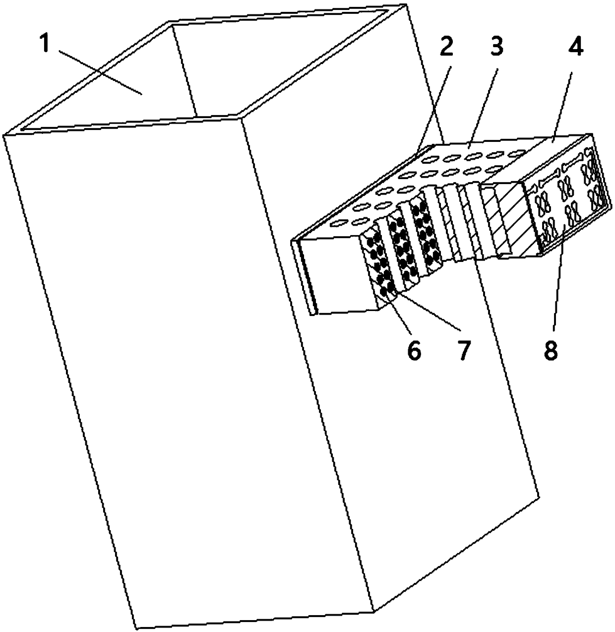
[0038] refer to Figure 1 to Figure 8 , a flue-outer wall temperature difference energy harvesting device, which collects heat energy in the flue, utilizes the temperature difference between the flue and the outer wall, and superimposes the Seebeck effect of the material through the energy harvesting device to obtain electrical energy, which can be used for ultra-low power Consumed energy building sensor nodes power supply.

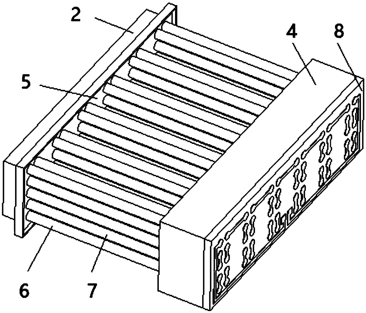
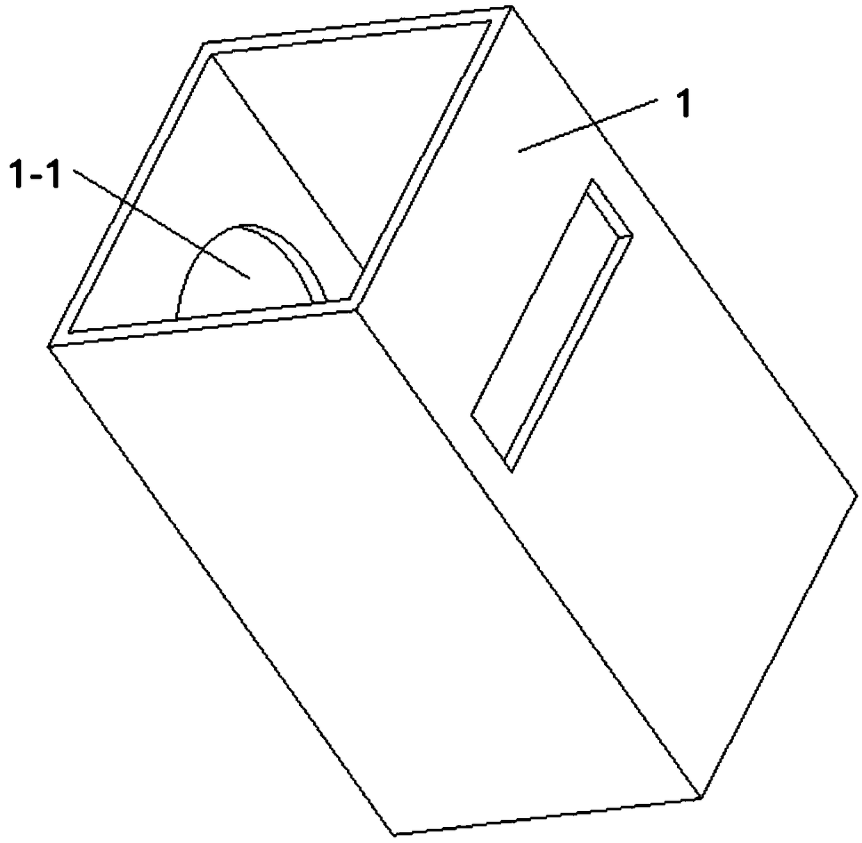
[0039] The energy harvesting device consists of the cement thin-wall flue exhaust 1 and the thermal insulation outer wall in sequence: heat collecting plate 2, flue side circuit board 5, two-way porous brick 3, perforated insulation layer 4 and outer wall side circuit board 8, wherein P-type cement-based Seebeck effect rods 6 and N-type cement-based Seebeck effect rods 7 are arranged in the bidirectional porous brick and the perforated insulation...


PUM


Abstract

The invention provides a flue-external wall temperature difference energy collecting device. The energy collecting device comprises a heat collecting plate, a flue-side circuit board, a bidirectionalporous brick, a perforated insulating layer and an external-wall-side circuit board which are sequentially arranged from the wall of a cement thin-wall discharge flue to an insulating external wall; P-type cement-based Seebeck effect bars and N-type cement-based Seebeck effect bars are arranged in the bidirectional porous brick and the perforated insulating layer. The flue-external wall temperature difference energy collecting device can conveniently and lastingly supply power to wireless sensor networks in an environment-friendly way.

Description

technical field [0001] The invention relates to an energy collection device in an intelligent building, in particular to a device for collecting energy by using the temperature difference between the flue and the outer wall of an intelligent civil building, which is used for powering a wireless sensor node of an intelligent building with low power consumption. Background technique [0002] In the future, a large number of sensor nodes will be distributed in smart buildings, such as indoor and outdoor temperature, humidity, illuminance, wind speed, and wind direction sensors. They all need to solve the problem of node power supply. There are usually two options. First, wiring to achieve power supply and transmission of measurement signals. Consider When it comes to the large number of sensors, the huge volume of the enclosure structure and the possible moving parts, the wiring design and construction costs are relatively high; second, the battery is powered, and the measuremen...

Claims


Application Information

Patent Timeline
Patent Type & Authority Applications(China)
IPC IPC(8): H02N11/00
CPCH02N11/002
Inventor 孙莹张端
Owner ZHEJIANG SCI-TECH UNIV
Learn More