Supercharge Your Innovation With Domain-Expert AI Agents!

Shoe rack adjustable in layer height

A shoe rack and height technology, applied in the direction of adjustable cabinets, wardrobes, home appliances, etc., can solve the problems of insufficient space utilization and single height, and achieve the effects of easy promotion, convenient operation and wide application.

Inactive Publication Date: 2018-10-16
阜南县润杨家居有限公司
View PDF0 Cites 0 Cited by
  • Summary
  • Abstract
  • Description
  • Claims
  • Application Information

AI Technical Summary

Problems solved by technology

[0004] The technical problem to be solved by the patent of the present invention is to provide a shoe rack with adjustable height of each layer, which effectively solves the above-mentioned existing problems such as the single height between the layers of the existing shoe rack and insufficient space utilization.

Method used


Image

  • Shoe rack adjustable in layer height
  • Shoe rack adjustable in layer height
  • Shoe rack adjustable in layer height

Examples


specific Embodiment approach 1

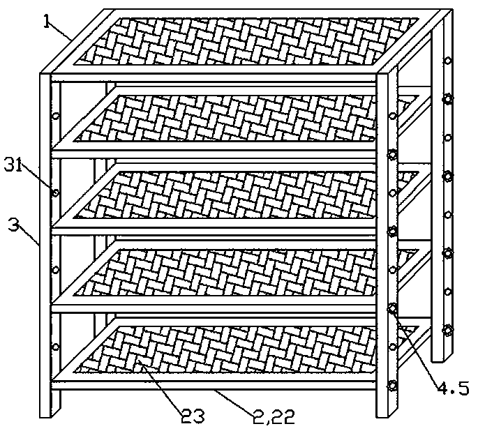
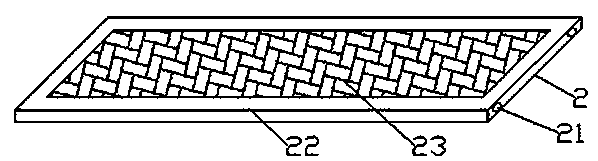
[0018] Such as figure 1 with 3 As shown, a shoe rack with adjustable height of each layer includes a rectangular shoe rack frame 1 and several laminates 2, and the laminates 2 are arranged inside the shoe rack frame 1; The support bar 3 is evenly provided with a number of through holes 31 along the up and down direction, and blind holes 21 are provided at the two ends of the laminate 2 corresponding to the vertical support bars 3 at the two ends of the shoe frame frame 1, and the laminate 2 passes through the vertical support bar 3. The blind holes 21 at both ends are correspondingly connected with the through holes 31 on the shoe rack frame 1 .

[0019] During the use of the shoe rack, according to the different styles and heights of household shoes, the distance between the layers of the boards 2 is adjusted, and then the blind holes 21 at both ends of the boards 2 and the through holes 31 on the shoe rack frame 1 are fixedly connected. , You can customize shoe racks of di...

specific Embodiment approach 2

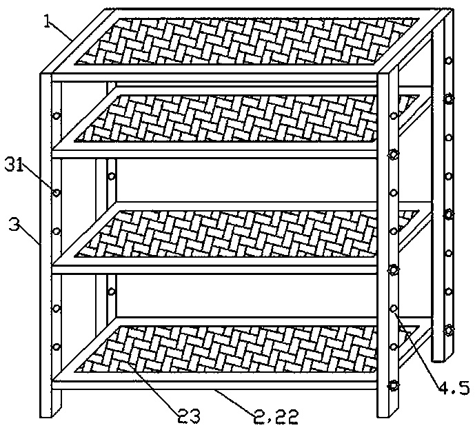
[0024] Such as figure 2 with 3 As shown, the two ends of the laminate 2 are connected to the vertical support rod 3 of the shoe rack frame 1 through a pin shaft 5 . Therefore, the pin shaft 5 can be used to facilitate disassembly, so as to realize the setting of different heights of the laminates 2 and the setting of different distances between the laminates 2 .

[0025] The patent of the present invention provides a shoe rack with adjustable height of each layer, which is simple in structure, easy to operate, and flexible and convenient to use; each family can adjust it according to the height of its own shoe style, which is suitable for storing and placing shoes of various heights and making full use of it. The shoe rack space is widely used and easy to promote.


PUM


Abstract

The invention discloses a shoe rack adjustable in layer height. The shoe rack comprises a rectangular shoe rack frame and multiple layer plates, and the layer plates are arranged in the shoe rack frame; multiple through holes are uniformly and vertically formed in vertical supporting rods at the two ends of the shoe rack frame, blind holes are formed in the portions, corresponding to the verticalsupporting rods at both ends of the shoe rack frame, of the two ends of each layer plate, and each layer plate is correspondingly connected to the through holes in the shoe rack frame through the blind holes in the two ends of the layer plate. The cross-sectional dimensions of the blind holes in the two ends of each layer plate are the same as those of the through holes in the vertical supportingrods of the shoe rack frame. The shoe rack adjustable in layer height is simple in structure, convenient to operate and convenient and flexible to use; each family can adjust the shoe rack according to the height and style of their own shoes, the shoe rack is suitable for storage and placement of the shoes different in height, the space of the shoe rack is fully utilized, and the shoe rack has a wide application range and is convenient to popularize.

Description

technical field [0001] The patent of the present invention relates to a shoe rack, in particular to a shoe rack with adjustable heights of each layer. Background technique [0002] In modern homes, shoe racks exist to ensure the cleanliness and easy management of shoes. With the continuous development of society, people's requirements for the quality of life are constantly improving. Among them, the necessities in home life are also various and more and more, and the home shoe racks are still various in style and exquisite in appearance. [0003] However, in various existing shoe racks, there is usually a fixed spacing between the layers of the shoe rack, so that there are requirements for the shoe styles applicable to each layer. Yet the styles of existing shoes exist in various ways, wherein there are shoes with heights such as slippers, sneakers, and sneakers that are shorter in height, and shoes with slightly higher heights such as short boots and high-heeled shoes, and...

Claims


Application Information

Patent Timeline
IPC IPC(8): A47B61/04A47B57/18A47B96/02
CPCA47B61/04A47B57/18A47B96/02
Inventor 杨浩
Owner 阜南县润杨家居有限公司
Features
  • R&D
  • Intellectual Property
  • Life Sciences
  • Materials
  • Tech Scout
  • Unparalleled Data Quality
  • Higher Quality Content
  • 60% Fewer Hallucinations
Learn More