
A control method for an injection molding machine

A control method and molding machine technology, applied in the field of injection molding machine control, can solve problems such as inconsistency in mold weight, inability to achieve effective and accurate production operations of injection molding machines, and imperfections.

Inactive Publication Date: 2018-10-16
VICTOR TAICHUNG MACHINERY WORKS
View PDF6 Cites 2 Cited by
  • Summary
  • Abstract
  • Description
  • Claims
  • Application Information

AI Technical Summary

Problems solved by technology

In this way, when the injection molding machine is controlled by the same parameters to perform the injection operation, the weight of the melt injected into the mold will not be consistent, resulting in the quality of the final product.
[0004] In addition, in addition to the above problems, during the production process of the injection molding machine, due to the high injection pressure of the material tube near the nozzle (at the glue head), part of the melt will flow back when the glue head group is closed. Screw, so that the actual injection volume does not match the expected, which leads to abnormalities in the finished product
[0005] Therefore, it can be seen from the above content that the conventional injection molding machine still cannot achieve effective and accurate production operations in injection control, and it is still not perfect and needs to be improved.

Method used


Image

  • A control method for an injection molding machine
  • A control method for an injection molding machine
  • A control method for an injection molding machine

Examples


Embodiment Construction

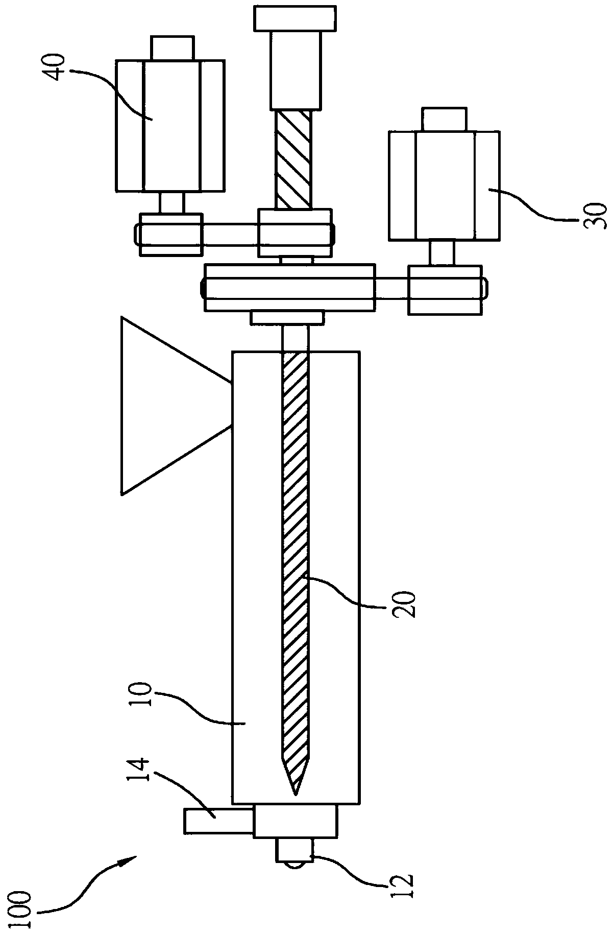
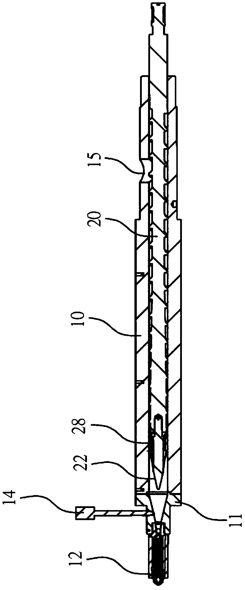
[0031] In order to illustrate the present invention more clearly, a preferred embodiment is given and described in detail with reference to the drawings. See figure 1 As shown, the control method of the present invention is used to apply to an injection molding machine 100. In this embodiment, a screw type injection molding machine is taken as an example, but it is not limited thereto. The injection molding machine 100 includes a material tube 10 , a feeding motor 30 and an injection motor 40 . continued figure 2 , the material pipe 10 has a material port 15 for inputting plastic, the front end of the material pipe 10 has a nozzle flange 11 connected to a nozzle 12, and the nozzle 12 is connected to a mold (not shown), and the The material tube 10 is provided with a pressure thermometer 14 near the nozzle 12 to measure the pressure and temperature in the material tube 10 close to the nozzle 12 (that is, the material storage area in the material tube 10 for storing melt glue...


PUM


Abstract

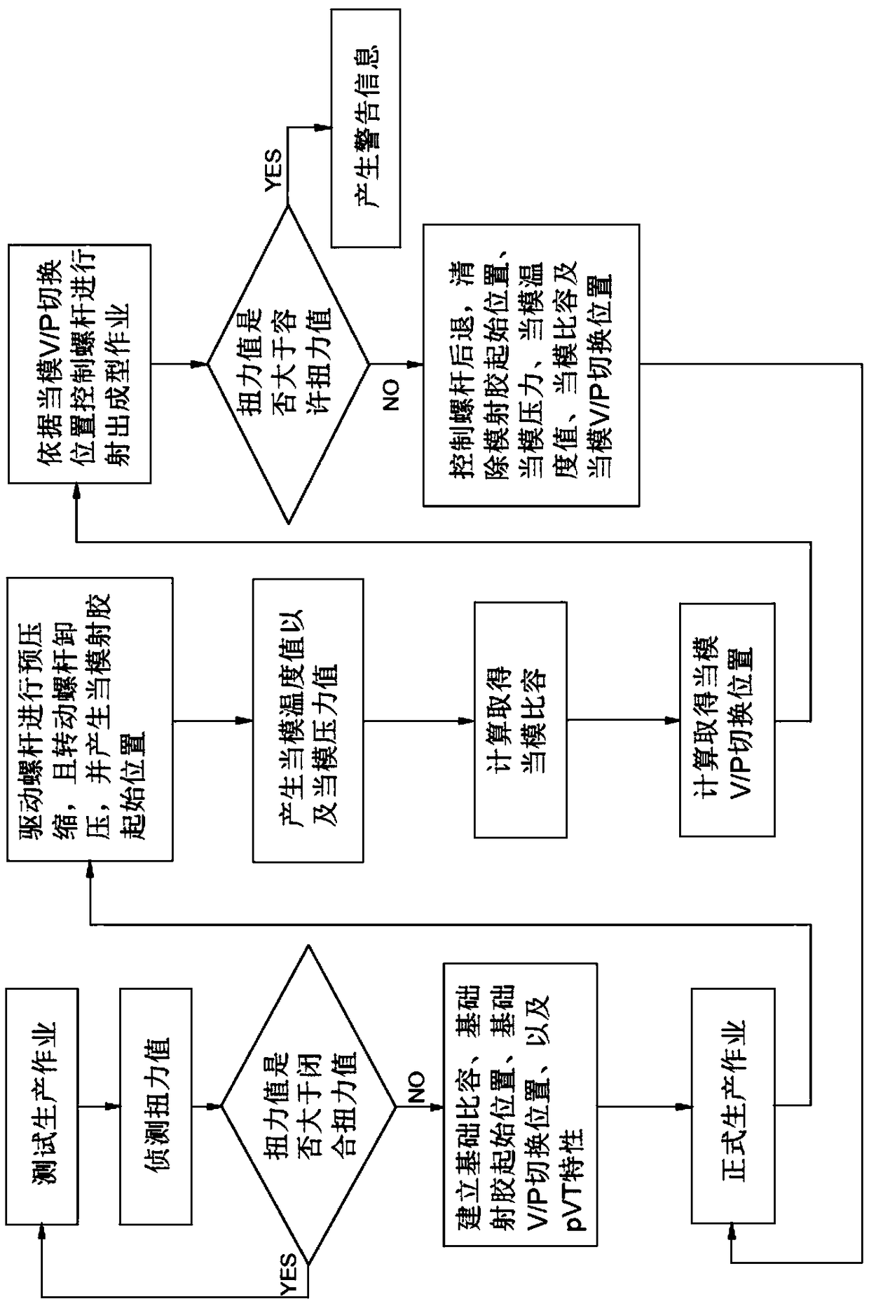
A control method for an injection molding machine, comprising the steps of: establishing a basic specific volume, a base injection starting position, a basic VP switching position, and a pVT characteristic; and then recording the position of a screw to generate a molding injection starting position; recording the pressure and temperature in a material tube to generate the mold pressure value and the mold temperature value; then calculating a mold specific volume according to the mold pressure value, the mold temperature value and the pVT characteristic; and calculating a mold VP switching position according to the molding injection starting position, the ratio between the mold specific volume and basic specific volume, and the difference between the base injection starting position and a basic VP switching position; finally, controlling the motor to drive the screw to move forward according to the information of the mold VP switching position. In this way, the VP switching point can beadjusted according to the specific value and position difference of each mode, thereby ensuring the uniform weight of the finished product.

Description

【Technical field】 [0001] The present invention relates to an injection molding machine; in particular, it refers to a control method of an injection molding machine. 【Background technique】 [0002] A general injection molding machine consists of a material tube and a screw. The screw drives the plastic in a rotating manner. After the plastic is melted in the material tube and turned into a melt, it is injected from the nozzle on the material tube to fill the inside of the mold. It is molded into a finished product of the desired shape, and the plastic can be stably molded even with a mold of a complex shape. Therefore, the industry has increasingly used injection molding machines as production machines for plastic and rubber products or electronic equipment parts. [0003] However, in practice, the injection molding machine still encounters some problems during the production process, which will affect the quality of the final product. For example, because the pressure and...

Claims


Application Information

Patent Timeline
IPC IPC(8): B29C45/76
CPCB29C45/76B29C2945/76545
Inventor 王立鼎
Owner VICTOR TAICHUNG MACHINERY WORKS
Learn More