Stroke controller with upper and lower limits

A technology of stroke controller and position limit, which is applied in the direction of load hanging components, hoisting devices, transportation and packaging, etc. It can solve the problems of difficult fixing of wire ropes, easy interference in winding, complex structure, etc., and achieves convenient use and maintenance. Good action reliability and lightweight structure

Inactive Publication Date: 2018-10-16
JIANGSU ZHAOSHENG ENVIRONMENTAL PROTECTION TECH CO LTD
View PDF2 Cites 0 Cited by
  • Summary
  • Abstract
  • Description
  • Claims
  • Application Information

AI Technical Summary

Problems solved by technology

[0003] Aiming at the above-mentioned problems existing in the existing upper and lower limit stroke controllers, such as complex structure, difficulty in fixing the wire rope well, and easy interference during winding, the applicant provides a rationally structured upper and lower limit stroke controller with a simple structure. Effectively avoid the interference phenomenon between the controller itself and the steel wire rope, with good operational reliability, convenient installation, use and maintenance, and realize the automatic limit protection function of the hoisting mechanism rising or falling

Method used


Image

  • Stroke controller with upper and lower limits
  • Stroke controller with upper and lower limits

Examples


Embodiment Construction

[0016] The specific implementation manner of the present invention will be described below in conjunction with the accompanying drawings.

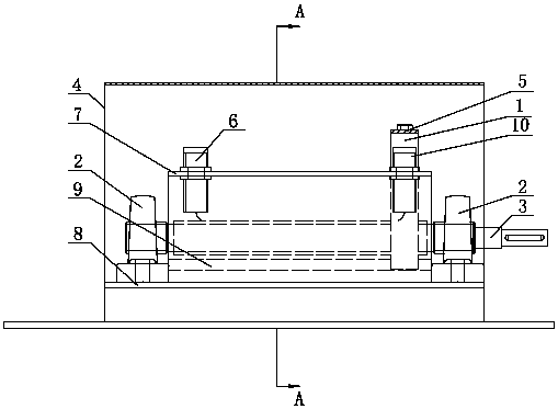
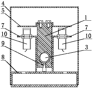
[0017] Such as figure 1 , figure 2 As shown, a horizontal base 8 is provided in the lower part of the housing 4 of the upper and lower limit stroke controller of the present invention, and two bearings 2 are provided on the left and right ends of the base 8 . The screw rod 3 is arranged between the two bearings 2 . The rear end of the screw rod 3 extends out of the casing 4, and the extension part is connected with the capstan shaft. A raised slide rail 9 is provided on the base 8 between the two bearings 2 . The moving slider 1 is vertical and arranged on the slide rail 9. The center of the bottom of the moving slider 1 is provided with a groove matching the protrusion of the slide rail 9. The threaded hole is matched on the screw mandrel 3. Such as figure 2 As shown, a horizontal proximity switch contact plate 5 is fixedly arrang...


PUM


Abstract

The invention discloses a stroke controller with upper and lower limits. The lower parts of the stroke controller with upper and lower limits is provided with a horizontal base; the base is provided with a slide rail; a moving slide block is movably arranged on the slide rail; a screw rod passes through the moving slide block and is movable arranged on the slide rail, and one end of the screw rodis connected with a winch shaft; the moving slide block is provided with a threaded hole matched with the size of peripheral threads of the screw rod, and the threaded hole is cooperatively arranged on the screw rod; proximity switch fixing plates are arranged on the base; the front end of each proximity switch fixing plate is provided with an upper limit signal collector, and the rear end of eachproximity switch fixing plate is provided with a lower limit signal collector; and proximity switch contact plates are fixedly arranged on the upper part of the moving slide block and have height corresponding to the height of the upper limit signal collectors and the lower limit signal collectors.. The stroke controller with upper and lower limits invention can effectively avoid the interferencephenomenon between the controller itself and a steel wire rope, has good motion reliability, and is convenient to install, use and maintain, improved in automation degree, light in structure and applicable to various occasions.

Description

technical field [0001] The invention relates to a controller used on a hoisting mechanism, in particular to a controller for up and down limit strokes. Background technique [0002] Under the positive and negative rotation of the motor, the hoisting mechanism can rise or fall by taking in or releasing the wire rope. In order to ensure safety, manual control is usually used to adjust the lifting length of the wire rope or to equip the motor with various limit protection devices. Chinese patent ZL200610053218 discloses a winding rope and travel limit device for electric roller blinds, which are fixed on the screw rod inside. The limit pin on the guide wheel cooperates with the limit pin fixed on the guide wheel to form a limit mechanism. This device is not only complex in structure, but also the setting of the embedding groove is difficult to ensure a good fixation with the wire rope, and the wire rope is prone to appear during use. Swimming phenomenon, thereby losing the mat...

Claims


Application Information

Patent Timeline
Patent Type & Authority Applications(China)
IPC IPC(8): B66C13/50B66D1/56
CPCB66C13/50B66D1/56
Inventor 周震球尹志强钱登
Owner JIANGSU ZHAOSHENG ENVIRONMENTAL PROTECTION TECH CO LTD
Why Eureka
Try Eureka