Diaphragm valve

A diaphragm and valve technology, applied in the field of diaphragm valves, can solve the problems of difficult installation, complex structure and production cost of diaphragm valves, and achieve the effects of good sealing effect, reduced use cost and simple control device.

Pending Publication Date: 2018-10-16
苏州巴恩斯通环保科技有限公司
View PDF0 Cites 0 Cited by
  • Summary
  • Abstract
  • Description
  • Claims
  • Application Information

AI Technical Summary

Problems solved by technology

[0004] The purpose of the present invention is to solve the problems of existing diaphragm valves, such as difficult installation, high production cost, complex structure and certain limitations, and provide a valve with simple structure, low manufacturing cost, large flow rate and good stability. diaphragm valve

Method used


Image

  • Diaphragm valve
  • Diaphragm valve
  • Diaphragm valve

Examples


Embodiment 1

[0024] Embodiment 1: a kind of diaphragm valve

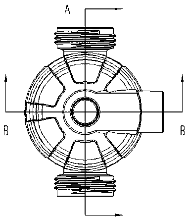
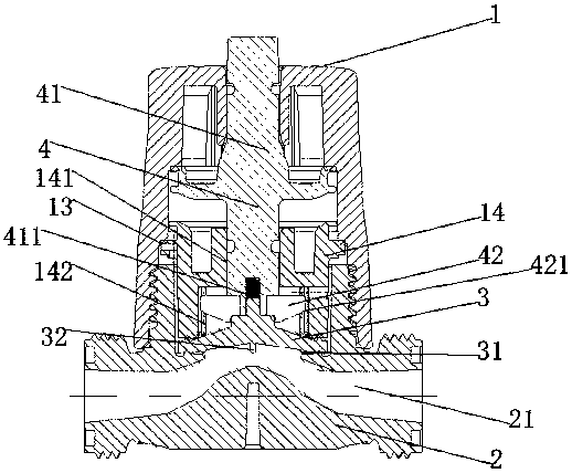
[0025] See Figure 1-4 , a diaphragm valve, comprising a housing 1, a valve seat 2, a diaphragm 3, and a control device 4;

[0026] The left and right sides of the valve seat 2 are provided with pipe connecting parts 21, and the position between the two pipe connecting parts 21 is in the shape of a roof;

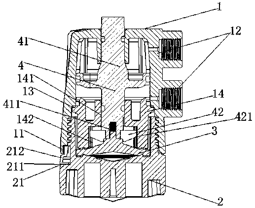
[0027] The upper part of the valve seat 2 is provided with threads, and one side of the upper part of the valve seat 2 is provided with a positioning device 21;

[0028] The positioning device 21 includes a groove A211 and a buckle 212;

[0029] The buckle 212 is L-shaped, the lower part of the bayonet is located at the bottom of the groove A211, the upper part of the buckle 212 is in the shape of a cuboid, and there is a gap between the inner side of the upper part of the buckle 212 and the groove 212, and the upper part of the buckle 212 The outer side is located on the outer side of the thread of the valve seat 2;

[00...

Embodiment 2

[0053] Embodiment 2: a kind of diaphragm valve

[0054] See Figure 1-4 , a diaphragm valve, comprising a housing 1, a valve seat 2, a diaphragm 3, and a control device 4;

[0055] The left and right sides of the valve seat 2 are provided with pipe connecting parts 21, and the position between the two pipe connecting parts 21 is in the shape of a roof;

[0056] The upper part of the valve seat 2 is provided with threads, and one side of the upper part of the valve seat 2 is provided with a positioning device 21;

[0057] The positioning device 21 includes a groove A211 and a buckle 212;

[0058] The buckle 212 is L-shaped, the lower part of the bayonet is located at the bottom of the groove A211, the upper part of the buckle 212 is in the shape of a cuboid, and there is a gap between the inner side of the upper part of the buckle 212 and the groove 212, and the upper part of the buckle 212 The outer side is located on the outer side of the thread of the valve seat 2;

[00...


PUM


Abstract

The invention discloses a diaphragm valve. The diaphragm valve comprises a shell, a valve seat, a diaphragm and a control device, wherein threads are arranged at the upper part of the valve seat; a positioning device is arranged on one side of the upper part of the valve seat; the shell is mounted on the valve seat; a diaphragm fixing cover is arranged in the shell; the control device comprises avalve rod and a pressing block; the valve rod is mounted on the diaphragm fixing cover; the pressing block is fixed at the end of the valve rod; the diaphragm is arranged between the diaphragm fixingcover and the valve seat and is mounted at the end of the valve rod through a fixing bolt; the diaphragm is bowl-shaped; sealing flanges are also arranged on the diaphragm. According to the diaphragmvalve, when the diaphragm valve is closed, a second flange on the diaphragm is firstly in contact with a ridge-shaped groove in a position between two pipeline connection parts, then the valve rod isfurther driven to move downwards, so that the second flange is extruded till the second flange is deformed; the sealing effect is excellent; through adoption of pneumatic control, the control device is simple; the usage cost is reduced; the diaphragm valve can be normally used under the condition that the environment is relatively harsh; the automatic control and the accuracy control are achieved.

Description

technical field [0001] The invention relates to the technical field of valves, in particular to a diaphragm valve. Background technique [0002] Valves are control components used to control fluid flow, pressure and flow direction, and have functions such as cut-off, adjustment, flow diversion, reverse flow prevention, and pressure stabilization. At present, the valve mainly includes a shell, a control device and an end cover. The shell and the end cover are usually connected by connecting parts such as screws. Although this connection method improves the installation accuracy of the valve, it increases the difficulty of valve installation. Improve the production cost of the valve; diaphragm valves generally include a connecting portion and a diaphragm pressure head, the connecting portion is a barrel-shaped structure, the lower end of which presses the diaphragm and is fixedly connected with the base, the The center of the top end of the diaphragm is provided with a limit ...

Claims


Application Information

Patent Timeline
IPC IPC(8): F16K7/17
CPCF16K7/17
Inventor 卫洋
Owner 苏州巴恩斯通环保科技有限公司
Why Eureka
Try Eureka