
Gate driving unit and display device

A gate drive and switching tube technology, applied in the field of gate drive units and display devices, can solve the problems of large power consumption and large coupling capacitance, and achieve the effect of reducing power consumption, reducing AC power consumption, and facilitating design

Active Publication Date: 2020-12-01
KUSN INFOVISION OPTOELECTRONICS
View PDF8 Cites 0 Cited by
  • Summary
  • Abstract
  • Description
  • Claims
  • Application Information

AI Technical Summary

Problems solved by technology

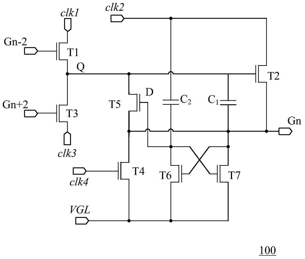
Since the gate drive signal Gn of this stage is used to drive the corresponding load, the switch tube T2 needs to provide a strong driving capability, so the size of the switch tube T2 will be significantly larger than other switch tubes in the gate drive unit, resulting in the switch tube T2 With large coupling capacitance
It can be seen that the power consumption of the gate driving unit 100 in the prior art mainly comes from the charging and discharging of the switching transistor T2 by the second clock signal clk2, and the large-sized switching transistor T2 will cause the gate driving unit 100 in the prior art to lose power. high power consumption

Method used


Image

  • Gate driving unit and display device
  • Gate driving unit and display device
  • Gate driving unit and display device

Examples


Embodiment Construction

[0029] Hereinafter, the present invention will be described in more detail with reference to the accompanying drawings. In the various figures, identical elements are indicated with similar reference numerals. For the sake of clarity, various parts in the drawings have not been drawn to scale. Also, some well-known parts may not be shown in the drawings.

[0030]In the following, many specific details of the present invention, such as structures, materials, dimensions, processes and techniques of components, are described for a clearer understanding of the present invention. However, the invention may be practiced without these specific details, as will be understood by those skilled in the art.

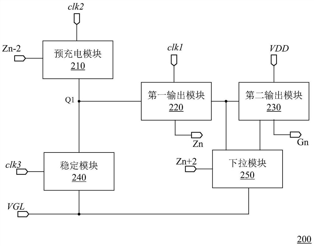
[0031] figure 2 A schematic structural diagram of the gate driving unit of the present invention is shown.

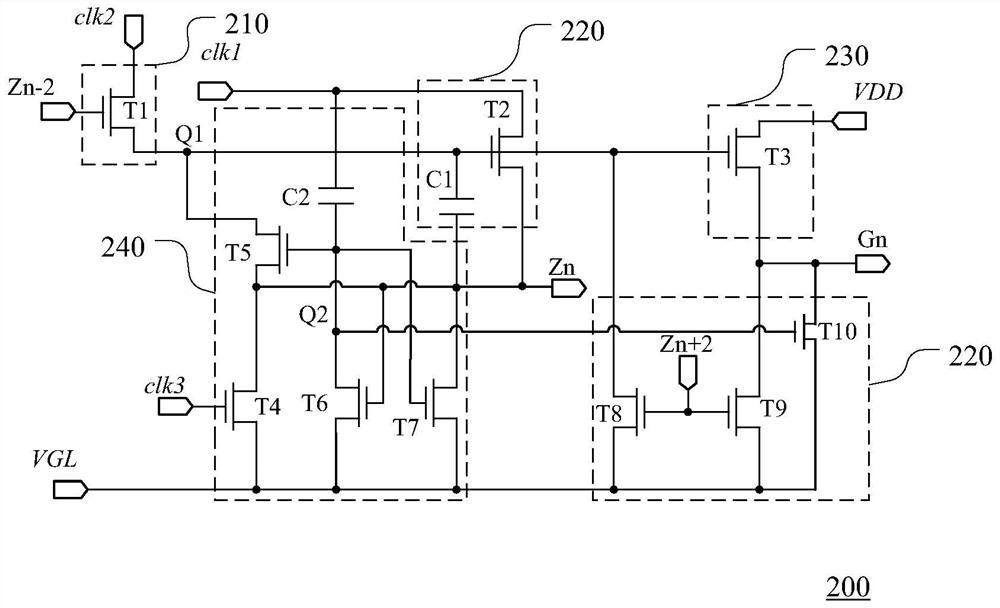
[0032] Such as figure 2 As shown, the gate driving unit 200 includes a pre-charging module 210 , a first output module 220 , a second output module 230 , a stabilizing ...


PUM


Abstract

The embodiment of the invention specifically discloses a gate drive unit and a display device. The gate drive unit includes a pre-charging module, a pull-down module, a first output module and a second output module. The pre-charging module is used for providing a pre-charging signal for a first node according to a front-stage transmission signal; the pull-down module is used for providing a low-voltage signal for the first node according to a rear-stage transmission signal; the first output module is connected to the pre-charging module and the pull-down module at the first node and used forgenerating a local-stage transmission signal according to the electric potential of the first node and a first clock signal; the second output module is connected to the first node and used for generating a local-stage gate drive signal according to the electric potential of the first node and a power source voltage signal. Therefore, large alternating current power consumption caused by the second output module is avoided, and the power consumption of the grate drive unit is directly reduced.

Description

technical field [0001] The present invention relates to the field of display technology, and more particularly relates to a gate driving unit and a display device. Background technique [0002] A liquid crystal display device is a display device that uses the phenomenon that the alignment direction of liquid crystal molecules changes under the action of an electric field to change the light transmittance of a light source. Due to the advantages of good display quality, small size and low power consumption, liquid crystal display devices have been widely used in mobile terminals such as mobile phones and large-sized display panels such as flat-panel televisions. Most of the liquid crystal displays currently on the market are projection type liquid crystal displays, which include a liquid crystal panel and a backlight module. The working principle of the liquid crystal panel is to place liquid crystal molecules between two parallel glass substrates, and apply a driving voltag...

Claims


Application Information

Patent Timeline
IPC IPC(8): G09G3/36
CPCG09G3/3696G09G2330/021
Inventor 柯中乔张鼎郭文豪段周雄
Owner KUSN INFOVISION OPTOELECTRONICS
Learn More