Rotary cutting tool

A cutting tool and fixture technology, applied in the direction of manufacturing tools, metal processing equipment, metal processing machinery parts, etc., can solve the problems of inability to meet the fixation, affecting the efficiency of workpiece cutting, and failing to meet the needs of use, to increase accuracy and Use efficiency, enhance processing efficiency, and meet the effect of use needs

Active Publication Date: 2018-10-16
利辛县宝隆橡塑密封件有限责任公司
View PDF3 Cites 3 Cited by
  • Summary
  • Abstract
  • Description
  • Claims
  • Application Information

AI Technical Summary

Problems solved by technology

[0002] As the electronic equipment industry pursues thinner and faster development, the processing requirements for printed circuit boards are getting higher and higher. Therefore, improving processing efficiency and processing accuracy is crucial to the development of the entire industry. For example, the application number is 201620105449.9 The patent includes a cutting part, the front end of the cutting part has a milling tip, the cutting part is provided with a first helical groove and a second helical groove, and the helical direction of the first helical groove and the second helical groove is uniform It is right-handed or both are left-handed. There are multiple first helical grooves and each of the first helical grooves is uniformly distributed along the circumferential direction of the cutting part. The second helical groove is provided with one and starts from the cutting part The front end of the front end is screwed to the other end. This patent cannot satisfy the need to fix the workpiece to be processed on the fixture, resulting in the inability to fix it and affecting the processing efficiency of the workpiece. It also cannot lead to accurate movement to the fixture, resulting in an impact on the workpiece. The efficiency of cutting affects the accuracy of cutting, which cannot meet the needs of users

Method used


Image

  • Rotary cutting tool
  • Rotary cutting tool
  • Rotary cutting tool

Examples


Embodiment Construction

[0018] The following will clearly and completely describe the technical solutions in the embodiments of the present invention with reference to the accompanying drawings in the embodiments of the present invention. Obviously, the described embodiments are only some, not all, embodiments of the present invention. Based on the embodiments of the present invention, all other embodiments obtained by persons of ordinary skill in the art without making creative efforts belong to the protection scope of the present invention.

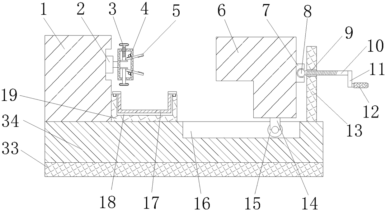
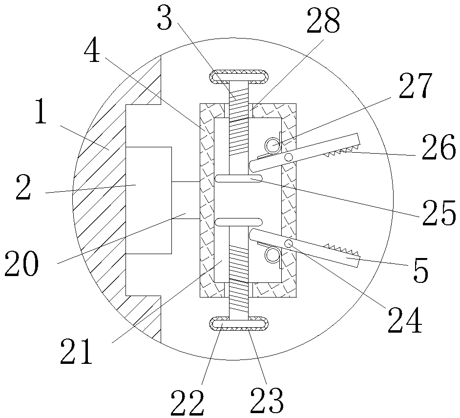
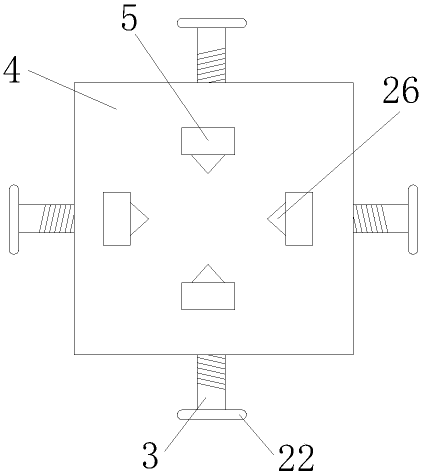
[0019] see Figure 1-4 , the present invention provides a technical solution: a rotary cutting tool, including a base 34, the base 34 is used to fix the body 1, the bottom end of the base 34 is fixedly connected with a pad 33, the pad 33 is used to support the base 34, the base 34 The top of the body 1 is fixedly connected to the body 1, and the center position on the right side of the body 1 is fixedly connected with a bearing 2. The connecting rod 20 is used...


PUM


Abstract

The invention discloses a rotary cutting tool. The rotary cutting tool includes a pedestal, and the top of the pedestal is fixed with a body. The central position on the right side of the body is fixed with a bearing, and the inner ring of the bearing is fixed with a connecting rod. The right side of the connecting rod is welded with a connecting block which is provided with a cavity therein, theinner right side of the cavity is provided with a clamp. The rotary cutting tool drives a first screw to move a block by rotating a rotating ring, so as to cause the block to squeeze and move the clamp. Therefore, the tool is convenient for fixing a work piece by the clamp effectively. At the same time, the work piece is prevented from being fixed unstably, which affects the efficiency of work piece processing. The processing efficiency of the rotary cutting tool is greatly enhanced. A second screw is driven to push the knife pedestal to move the knife pedestal right to the clamp by rotating ahandle. Therefore, the tool is convenient for cutting the work piece on the clamp effectively, and also increases the precision and efficiency of cutting the work piece.

Description

technical field [0001] The invention relates to the technical field of rotary cutting tools, in particular to a rotary cutting tool. Background technique [0002] As the electronic equipment industry pursues thinner and faster development, the processing requirements for printed circuit boards are getting higher and higher. Therefore, improving processing efficiency and processing accuracy is crucial to the development of the entire industry. For example, the application number is 201620105449.9 The patent includes a cutting part, the front end of the cutting part has a milling tip, the cutting part is provided with a first helical groove and a second helical groove, and the helical direction of the first helical groove and the second helical groove is uniform It is right-handed or both are left-handed. There are multiple first helical grooves and each of the first helical grooves is uniformly distributed along the circumferential direction of the cutting part. The second he...

Claims


Application Information

Patent Timeline
Patent Type & Authority Applications(China)
IPC IPC(8): H05K3/00B23Q3/06
Inventor 张锋
Owner 利辛县宝隆橡塑密封件有限责任公司
Why Eureka
Try Eureka