
Ground cleaning device for factory

A ground cleaning and factory technology, applied in cleaning equipment, cleaning machinery, applications, etc., can solve the problems of long time consumption and low work efficiency, and achieve the effect of increasing the cleaning range and reducing the work intensity

Active Publication Date: 2018-10-19
临沂兴创达知识产权运营有限公司
View PDF6 Cites 2 Cited by
  • Summary
  • Abstract
  • Description
  • Claims
  • Application Information

AI Technical Summary

Problems solved by technology

[0002] In the garbage collection devices that are often used on the market at present, although the automatic collection of garbage and the work of floor cleaning can be completed, because the garbage can only be cleaned at the bottom of the cart chassis during the garbage collection process, it takes a long time and work to clean the garbage. The efficiency is low, so this factory floor cleaning device is designed

Method used


Image

  • Ground cleaning device for factory
  • Ground cleaning device for factory
  • Ground cleaning device for factory

Examples


specific Embodiment approach 1

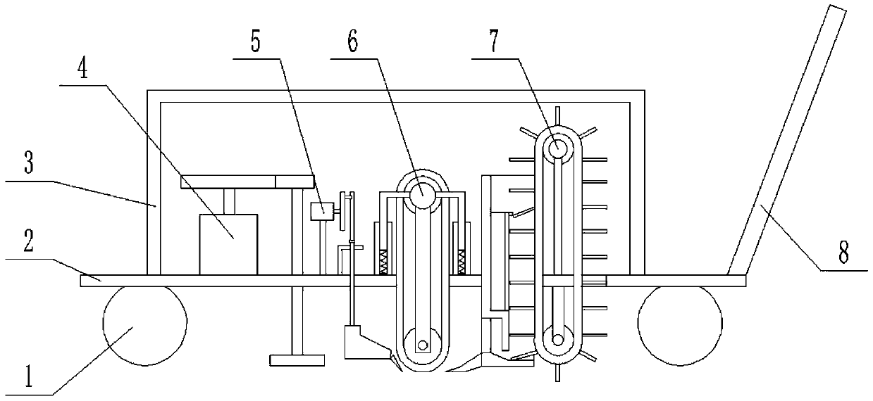
[0032] Combine below figure 1 , 2 , 3, 4, 5, 6, 7, 8, 9, 10, 11 illustrate this embodiment, the present invention relates to a cleaning device, more specifically a factory floor cleaning device, including a wheel 1, a bottom plate 2 , shell 3, garbage collection device 4, blocking device 5, garbage propulsion device 6, garbage collection device 7, push handle 8, not only can gather the garbage near the bottom plate to the lower end of the bottom plate through the garbage collection device, and increase the cleaning range of the device on the ground , and can automatically collect the gathered garbage into the garbage chute, reducing the work intensity of the staff.

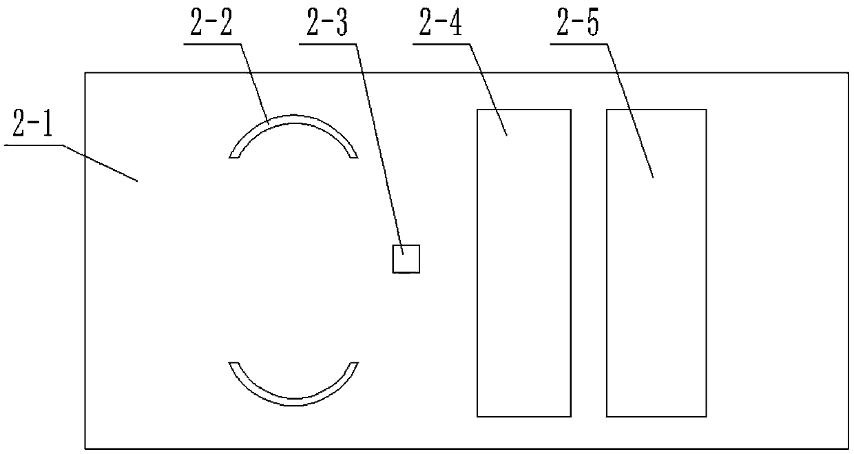
[0033] The base plate 2 is composed of a base plate main body 2-1, an arc groove 2-2, a through hole I2-3, a through hole II2-4, and a through hole III2-5; the left side of the base plate main body 2-1 is provided with an arc slot 2-2, and there are two arc-shaped slots 2-2, and the two arc-shaped slots 2-2 are ...

specific Embodiment approach 2

[0039] Combine below figure 1 , 2 , 3, 4, 5, 6, 7, 8, 9, 10, and 11 describe this embodiment, and this embodiment will further describe Embodiment 1. The motor I4-5 is provided with a forward and reverse control circuit inside.

specific Embodiment approach 3

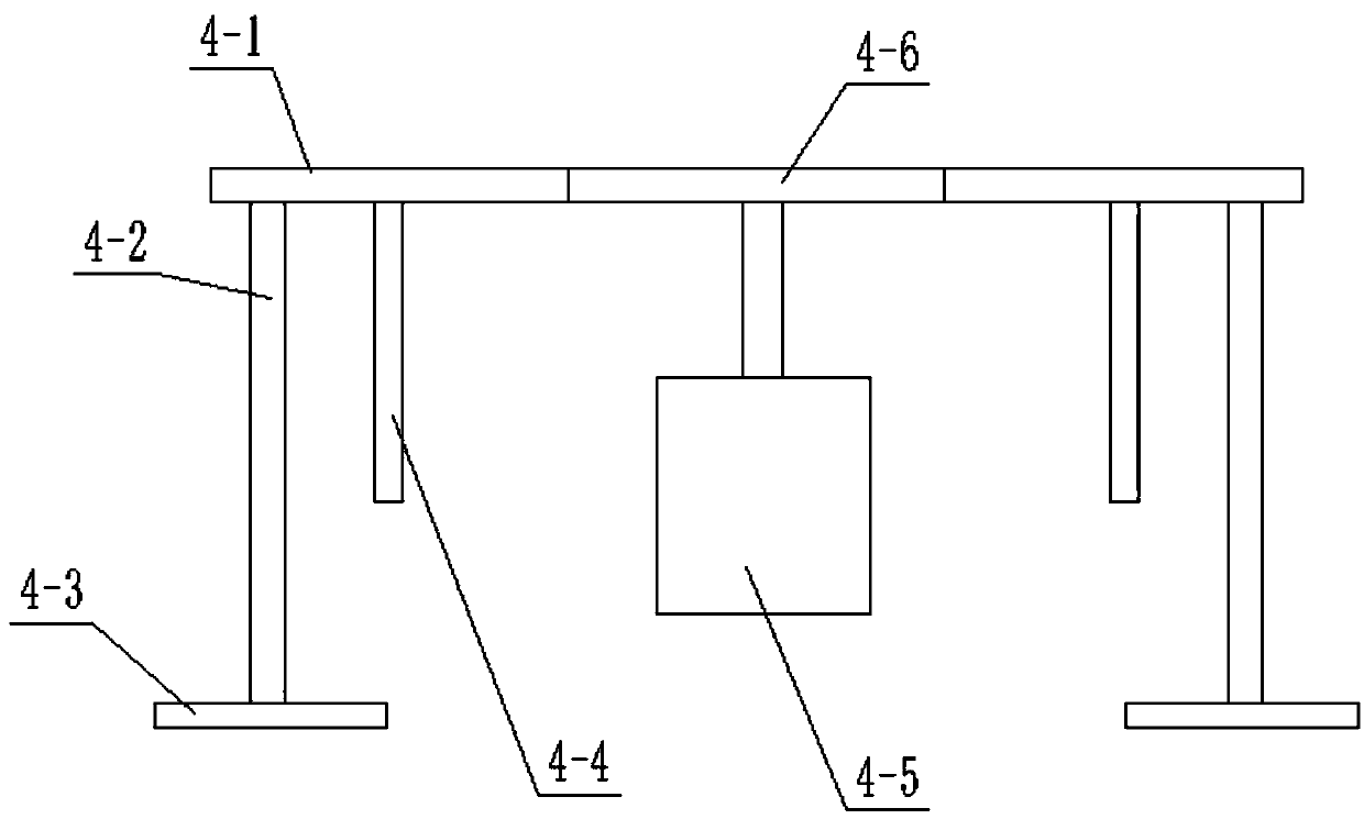
[0040] Combine below figure 1 , 2 , 3, 4, 5, 6, 7, 8, 9, 10, and 11 illustrate this embodiment, and this embodiment will further describe Embodiment 1. The part with teeth on the side of the runner 4-1 accounts for the portion of the runner 4 -1 third of the side.


PUM


Abstract

The invention relates to a cleaning device, in particular to a ground cleaning device for a factory. On one hand, garbage near a base plate can be gathered to the lower end of the base plate through agarbage gathering device, and the cleaning range of the device to the ground is increased; on the other hand, the gathered garbage can be collected into a garbage chute automatically, and the work intensity of workers is reduced. The right end of a spring I is connected into an arc-shaped groove; a motor support I is connected to the upper end of the base plate through welding, and a connecting rod III is in clearance fit with a through hole I; a limiting rod is connected to the upper end of the base plate through welding; the lower end of a cylinder is connected to the upper end of the baseplate through welding, and a conveyor belt I on a garbage pushing device is in clearance fit with a through hole II; a support block is connected to the upper end of the base plate through welding; acollection box shell is connected into a through hole III formed in the base plate through welding; a motor support III is connected to the upper end of the base plate through welding; a roller support is connected to the lower end of the base plate through welding; an object sloping plate makes contact with the ground.

Description

technical field [0001] The invention relates to a cleaning device, in particular to a factory floor cleaning device. Background technique [0002] In the garbage collection devices that are often used on the market at present, although the automatic collection of garbage and the work of floor cleaning can be completed, because the garbage can only be cleaned at the bottom of the cart chassis during the garbage collection process, it takes a long time and work to clean the garbage. The efficiency is low, so this factory floor cleaning device is designed. Contents of the invention [0003] The invention provides a floor cleaning device for factories, which has the beneficial effect that not only can the garbage near the bottom plate be gathered to the lower end of the bottom plate through the garbage collection device, and the cleaning range of the device on the ground can be increased, but also the gathered garbage can be automatically collected into the garbage tank To re...

Claims


Application Information

Patent Timeline
IPC IPC(8): A47L11/24A47L11/40
CPCA47L11/24A47L11/40A47L11/4013
Inventor 邹福灶
Owner 临沂兴创达知识产权运营有限公司
Features
  • Generate Ideas
  • Intellectual Property
  • Life Sciences
  • Materials
  • Tech Scout
  • Unparalleled Data Quality
  • Higher Quality Content
  • 60% Fewer Hallucinations
Learn More