Supercharge Your Innovation With Domain-Expert AI Agents!

Stamping device for finger spinner

A technology of stamping device and gyroscope, applied in the field of stamping device, can solve problems such as low production efficiency, and achieve the effect of improving work efficiency and assembly accuracy

Pending Publication Date: 2018-10-19
HEYUAN POLYTECHNIC
View PDF22 Cites 2 Cited by
  • Summary
  • Abstract
  • Description
  • Claims
  • Application Information

AI Technical Summary

Problems solved by technology

[0005] The technical problem to be solved by the present invention is to provide a stamping device for a fidget spinner aiming at solving the problem of low production efficiency caused by manually assembling the bearings of a fidget spinner in the prior art.

Method used


Image

  • Stamping device for finger spinner
  • Stamping device for finger spinner
  • Stamping device for finger spinner

Examples


Embodiment Construction

[0022] In order to make the object, technical solution and advantages of the present invention more clear and definite, the present invention will be further described in detail below with reference to the accompanying drawings and examples. It should be understood that the specific embodiments described here are only used to explain the present invention, not to limit the present invention.

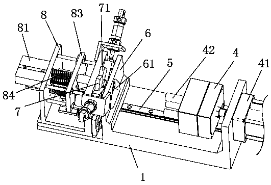
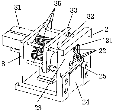
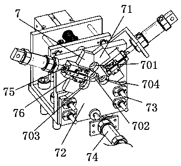
[0023] Please also see Figure 1-Figure 4 ,in, figure 1 It is a structural schematic diagram of the stamping device for fidget spinner according to the present invention; figure 2 It is a reference diagram of the use state when the jacking device of the present invention cooperates with the punching device; image 3 is a schematic structural view of the clamping device of the present invention; Figure 4 It is a reference diagram of the cooperation state of the holding device, the clamping device and the receiving plate when the loading is completed in the present invention.

[0024...


PUM


Abstract

The invention discloses a stamping device for a finger spinner. The stamping device for the finger spinner comprises a horizontally arranged base. The base is sequentially provided with a jacking device, a stamping substrate, a clamping device and a stamping mechanism. One side of the stamping substrate is provided with a groove for containing a finger spinner shell. The bottom of the groove is provided with an assembling hole corresponding to an inner hole of the finger spinner shell. The jacking device penetrates the assembling hole from the other side of the stamping substrate and jacks thefinger spinner shell. The clamping device clamps a bearing and positions the bearing at the position corresponding to the inner hole of the finger spinner shell. The stamping mechanism stamps the bearing into the inner hole of the finger spinner shell in the horizontal direction, stamping assembling of the finger spinner shell and the bearing is completed, mechanization is used in the whole stamping process, workers are not needed to work or conduct operation, and the working efficiency and the assembling precision are improved.

Description

technical field [0001] The invention relates to the technical field of stamping devices, in particular to a stamping device for fidget spinners. Background technique [0002] With the continuous development of society and the continuous progress of science and technology, mechanization, automation, and standardized production have gradually become the development trend, while the traditional manual method has become increasingly unable to meet the development requirements of the times. [0003] During the assembly process of the fidget spinner, a bearing needs to be installed in its inner hole, and the bearing is pressed into the inner hole by pressing. In the prior art, the assembly of the bearing and the fidget spinner is manually operated by workers. It is inevitable that there will be a sense of fatigue during the time-consuming assembly process, resulting in a reduction in production efficiency, and because each worker has individual differences, it is easy to cause dif...

Claims


Application Information

Patent Timeline
IPC IPC(8): B23P19/02
CPCB23P19/02
Inventor 黄文汉张秋容朱俊杰徐艺沈小华罗霞缤
Owner HEYUAN POLYTECHNIC
Features
  • R&D
  • Intellectual Property
  • Life Sciences
  • Materials
  • Tech Scout
  • Unparalleled Data Quality
  • Higher Quality Content
  • 60% Fewer Hallucinations
Learn More