Flexible supporting clamp system for complex revolved body thin-walled workpiece molded surface

A fixture system and technology for thin-walled parts, which is applied in the field of flexible supporting fixture systems for complex rotary thin-walled parts, can solve problems such as difficulty in adapting to mass production, inability to process, and inability to collect fixtures, etc., to achieve lifting and clamping And the effect of production efficiency, improvement of recycling efficiency, and shortening of production cycle

Active Publication Date: 2018-10-19
XI AN JIAOTONG UNIV
View PDF6 Cites 9 Cited by
  • Summary
  • Abstract
  • Description
  • Claims
  • Application Information

AI Technical Summary

Problems solved by technology

The traditional mechanical support fixture device is complicated, the processing time is long, the adaptability to the parts is poor, and the working condition data of the fixture cannot be collected, and the processing status cannot be monitored. At present, the main measures to improve the rigidity of the complex rotary thin-walled parts are The inside of the part is filled with paraffin or low-melting point metal. During the filling process, it is necessary to seal the thin-walled hollow and complex rotary body. After the processing is completed, the paraffin or low-melting point metal is melted and flowed out. The whole process is complicated, energy consumption is high, and efficiency is high. Low, long processing cycle, high cost, difficult to adapt to mass production

Method used


Image

  • Flexible supporting clamp system for complex revolved body thin-walled workpiece molded surface
  • Flexible supporting clamp system for complex revolved body thin-walled workpiece molded surface
  • Flexible supporting clamp system for complex revolved body thin-walled workpiece molded surface

Examples


Embodiment Construction

[0024] The present invention will be described in detail below in conjunction with the accompanying drawings and embodiments, so that the advantages and features of the present invention can be more easily understood by those skilled in the art, so that the protection scope of the present invention can be defined more clearly.

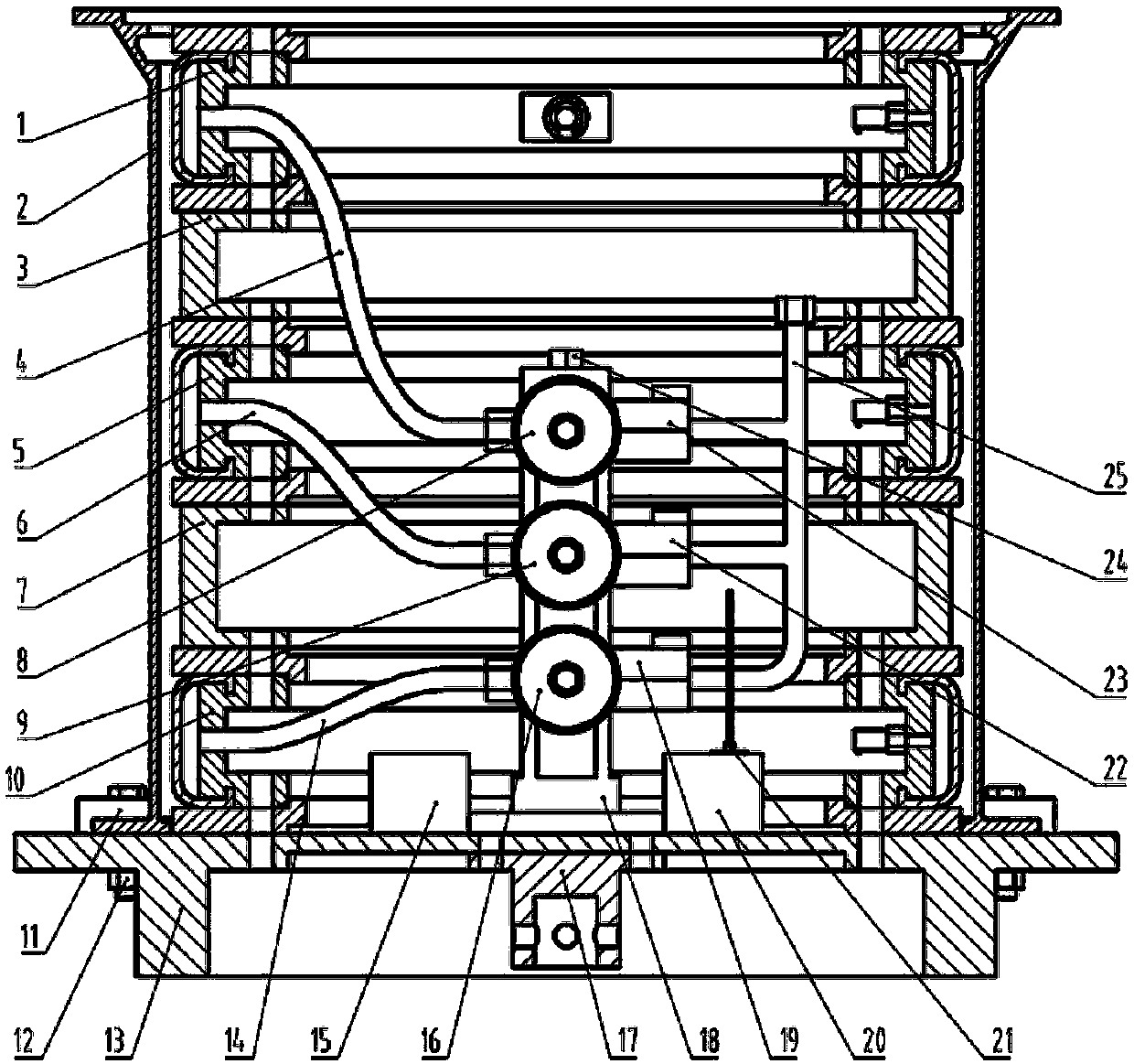
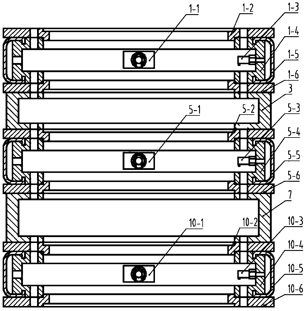
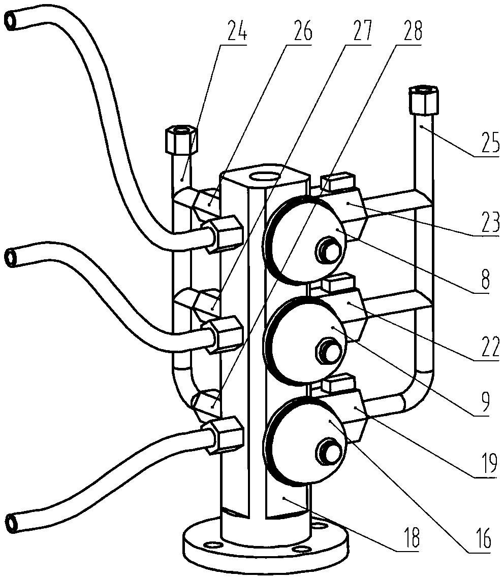
[0025] refer to figure 1 , figure 2 , image 3 , Figure 4 , Figure 5 and Figure 6 , a flexible support fixture system for complex rotary thin-walled parts, including an installation base 13, a hoisting flange 17 is fixed on the bottom of the installation base 13, and a complex installation is connected to the upper part of the installation base 13 through a fixing block 11 and an installation bolt 12. The thin-walled part 2, the installation base 13 inside the complex thin-walled part 2 is fixed with the third rubber bag expansion part 10, and the second rubber bag expansion part 10 connected to the third rubber bag expansion part 10 is install...


PUM


Abstract

The invention provides a flexible supporting clamp system for a complex revolved body thin-walled workpiece molded surface. The flexible supporting clamp system comprises an installation foundation support with the bottom being fixedly provided with a lifting flange, the upper portion of the installation foundation support is connected with a complex thin-walled workpiece, and the portion, insidethe complex thin-walled workpiece, of the installation foundation support is fixedly provided with a third rubber bag bulging component. The third rubber bag bulging component is provided with a second rubber bag bulging component, and the second rubber bag bulging component is provided with a first rubber bag bulging component. The portion, inside the complex thin-walled workpiece, of the installation foundation support is fixedly provided with a controller and a hydraulic installation seat, and the hydraulic installation seat is fixedly provided with three hydraulic energy accumulators fromtop to bottom in sequence. Each hydraulic energy accumulator, each electromagnetic overflowing valve and each one-way valve are fixed to the hydraulic installation seat and connected with inner flow channels of the hydraulic installation seat, and the inner flow channels of the hydraulic installation seat are connected with sealing cavities of the rubber bag bulging components through hydraulic pipes. Mechanical-hydraulic type clamping is adopted, clamping efficiency is high, clamping rigidity is large, real-time connection is performed under the machining state, and the machining rigidity andprecision of parts can be improved.

Description

technical field [0001] The invention relates to the technical field of manufacturing thin-walled parts of a revolving body, in particular to a surface flexible support fixture system for thin-walled parts of a complex revolving body. Background technique [0002] Thin-walled parts of complex rotary bodies are mostly composed of features with different structural and functional requirements. Subject to functional requirements, complex thin-walled parts often have complex structures, large diameters, thin walls, and poor overall rigidity. Under these circumstances, parts need to rotate. Due to high cutting temperature, high cutting force, severe tool wear, etc., it is easy to generate vibration and cutting deformation. How to realize precision machining on its surface has always been a technical difficulty in the field of processing and manufacturing technology. [0003] Vibration caused by insufficient workpiece rigidity due to unreasonable clamping and deformation of thin-wa...

Claims


Application Information

Patent Timeline
Patent Type & Authority Applications(China)
IPC IPC(8): B23Q3/08
CPCB23Q3/065B23Q3/082
Inventor 张琦马保伟徐宏图古玺马旭
Owner XI AN JIAOTONG UNIV
Why Eureka
Try Eureka