Movable 3D printing system

A 3D printing and 3D printer technology, applied in the field of 3D printing, can solve problems such as molding failure, inability to print, insufficient precision and surface quality, etc., to achieve the effect of expanding application scenarios, shortening delivery cycle, and improving 3D printing efficiency

Inactive Publication Date: 2018-10-19
BEIJING UNIV OF CHEM TECH
View PDF3 Cites 0 Cited by
  • Summary
  • Abstract
  • Description
  • Claims
  • Application Information

AI Technical Summary

Benefits of technology

The technical effect of this patented technology is an improved method called Mobile Three Dimensional Printing System(TM) used in creation of 3dprintable objects such as clothing items through 3D digital printing processes. It uses a special type of machine called a Mechanism Panel® mounted onto different types of carriers like cars, buses, boats, spacecraft, and humans. By adjusting its orientation based upon factors like acceleration or rotation speed, it allows the robot's movements to move smoothly without tilting upward due to gravity. Additionally, there are also features described where the Machine Plane Tilt Angle remains constant regardless of how fast they rotate around their own axis. These improvements make the 3rdyeasty printings more efficient while reducing production time compared to traditional methods.

Problems solved by technology

This patented describes how three dimensional (3D) printing can affect productivity when there are movements that cause changes in orientation or weight on the printable material before they reach their destination. These issues may result in poorly formed surfaces with defective dimensions for certain applications such as electronic devices.

Method used


Image

  • Movable 3D printing system
  • Movable 3D printing system
  • Movable 3D printing system

Examples


Embodiment Construction

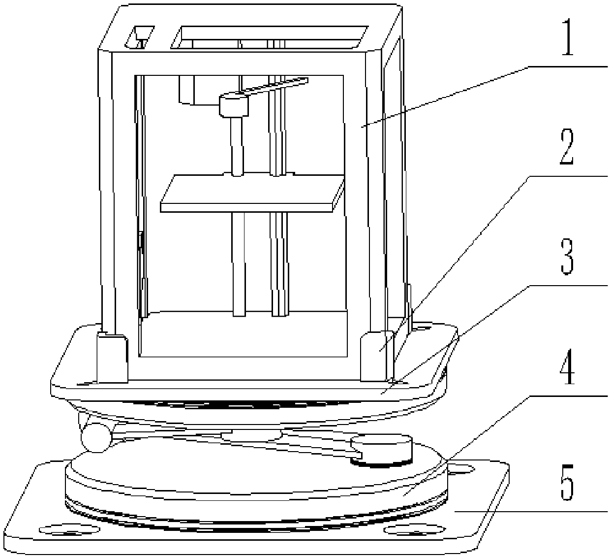
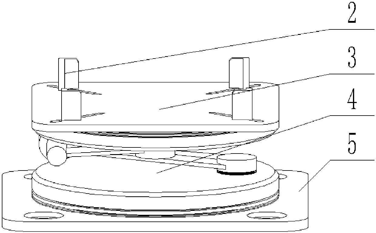
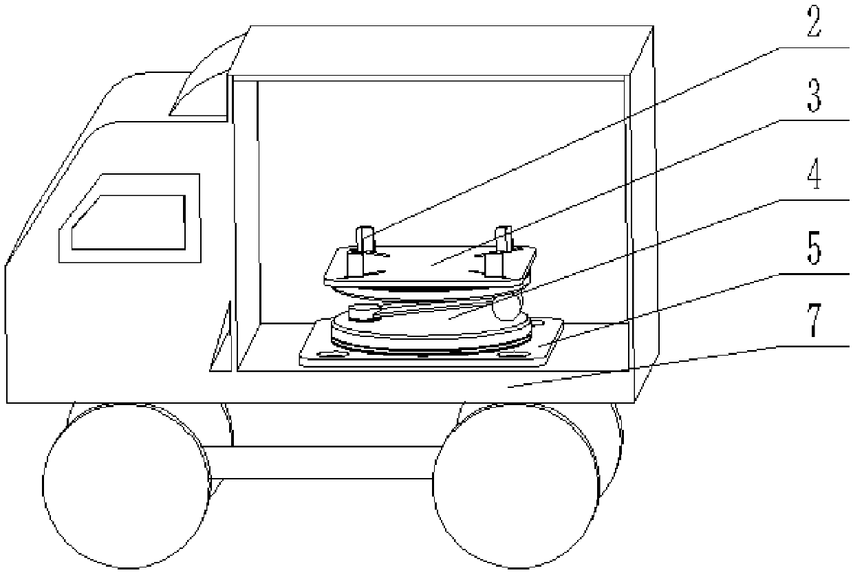
[0016] The present invention proposes a mobile 3D printing system, such as figure 1 As shown, it consists of a 3D printer 1, a mechanical pan / tilt 4, a spring holder 2, a 3D printer installation platform 3, a pan / tilt installation base 5 and a transport vehicle 7.

[0017] The working mode of a mobile 3D printing system of the present invention is: the 3D printer installation platform is installed on the top of the mechanical platform 4 . The 3D printer 1 is placed in the middle of the 3D printer installation platform 3, and the four corners of the platform are provided with spring holders 2. The body is installed on the central position of the 3D printer installation platform 3. The spring fixer 2 can move a certain distance in the diagonal direction of the 3D printer installation platform 3, so that the mechanical platform 4 (such as figure 2 shown) are suitable for different sizes of 3D printers1. The mechanical pan-tilt 4 is connected to the load-bearing back frame 6 o...


PUM


Abstract

The invention discloses a movable 3D printing system composed of a 3D printer, a mechanical pan-tilt, spring fixators, a 3D printer mounting platform, a pan-tilt mounting base and a transport carrier.The 3D printer mounting platform is mounted at the top of the mechanical pan-tilt. The 3D printer is placed on the 3D printer mounting platform, and the spring fixators at the four corners of the platform enable the 3D printer to be fixed to the center of the 3D printer mounting platform. The mechanical pan-tilt is connected with a bearing back frame or a warehouse bottom plate of a transport tool through the pan-tilt mounting base. When the transport tool is turned, accelerated, decelerated and rise or fall, an included angle is formed between the normal direction and the gravity direction of the warehouse bottom plate; or when a human body leans forward, bends down and shakes, a dip angle is formed between the normal and the gravity direction of a bottom plate of the bearing back frame.The mechanical pan-tilt conducts motion compensation on the 3D printer mounting platform so that the normal direction and the gravity direction of a 3D printing forming platform are always overlapped, and stable work of the 3D printer in the motion process is maintained.

Description


Claims


Application Information

Patent Timeline
Owner BEIJING UNIV OF CHEM TECH
Why Eureka
Try Eureka