Steel pipe transport truck

A technology of steel pipes and trucks, which is applied in transportation and packaging, vehicles used to carry long goods, vehicles used for freight, etc. It can solve problems such as easy shaking, potential safety hazards, unfavorable steel pipe protection, etc., and achieve stable placement Effect

Active Publication Date: 2018-10-19
凤阳合联兴工程机械有限公司
View PDF6 Cites 2 Cited by
  • Summary
  • Abstract
  • Description
  • Claims
  • Application Information

AI Technical Summary

Problems solved by technology

[0002] In real daily life, it is often seen that round steel pipes are transported by small trucks at the construction site. ) steel pipes are placed obliquely between the front carr

Method used


Image

  • Steel pipe transport truck
  • Steel pipe transport truck
  • Steel pipe transport truck

Examples


Embodiment 1

[0046] Embodiment 1, that is, the first steel pipe placement scheme provided by the present invention is:

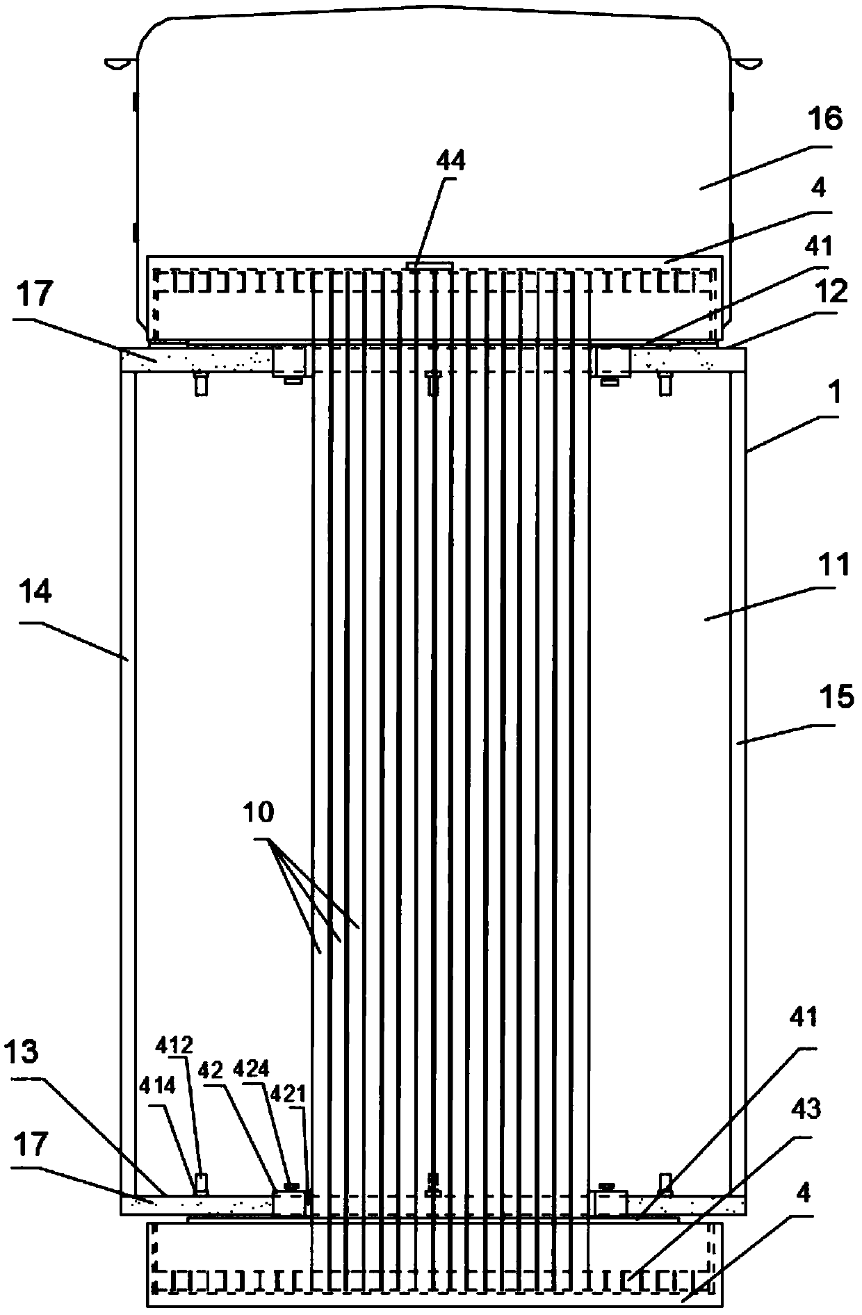
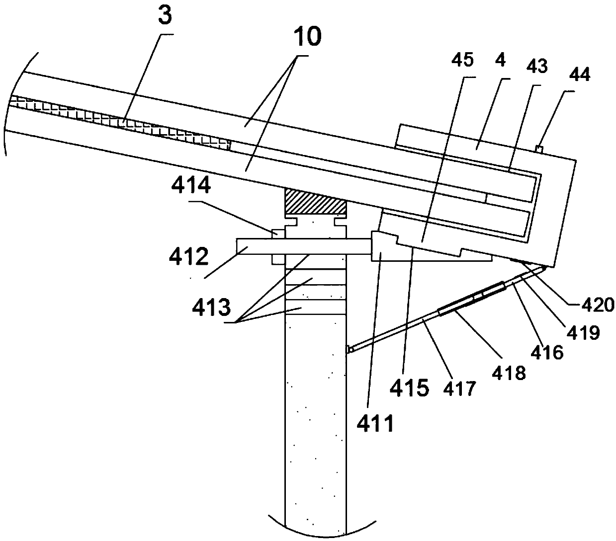
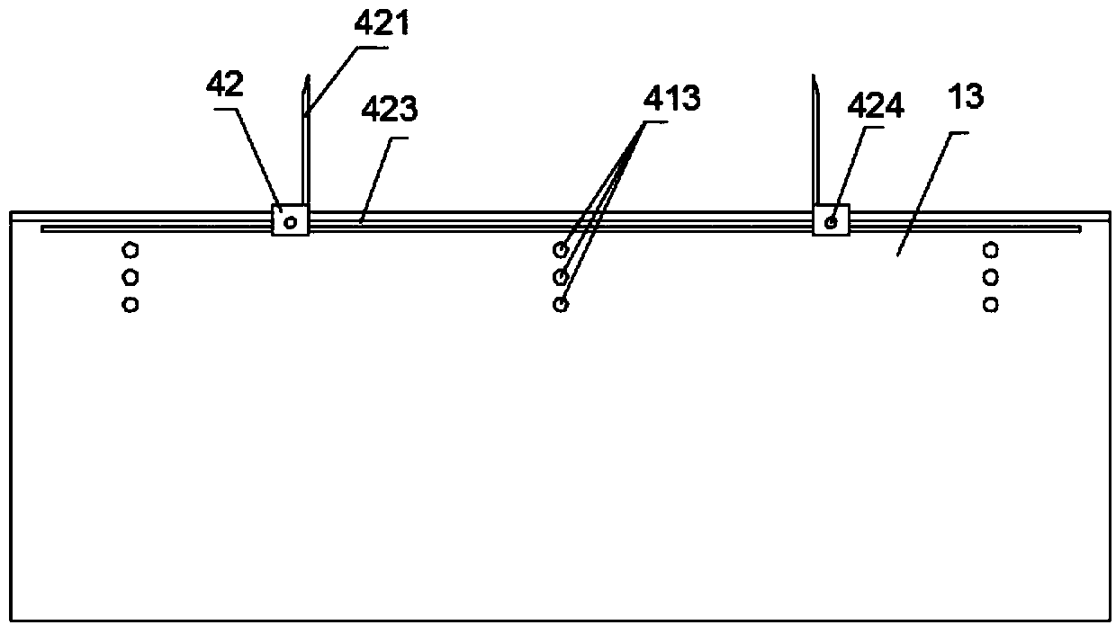
[0047] refer to Figure 1 to Figure 4 , the top surface of the front frame 12 and the top surface of the rear side plate 13 are all fixed with a layer of rubber anti-skid pad 17, and the front frame 12 and the rear side plate 13 can be connected to the limited seat 42 in a laterally movable manner. A limited spacing is formed between the limiting seats 42, and one end of each limiting seat 42 corresponding to the limiting spacing is fixed with a vertically distributed limiting plate 421, specifically: the limiting seats 42 are provided with cavities 425 Inverted U-shaped structure with sliding parts 422 extending inwards at both ends respectively, sliding grooves 423 corresponding to sliding parts 422 are provided on the sides of the front frame 12 and rear side panel 13 respectively, and the position limiting The seat 42 is connected to the front frame 12 and the rear ...

Embodiment 2

[0053] Embodiment 2, the second steel pipe placement scheme provided by the present invention is:

[0054] refer to Figure 7 to Figure 9 As shown, a placement box 5 is fixed on the front side of the front frame 12, and several placement grooves 51 corresponding to the steel pipes 10 are embedded in the placement box 5, and the rear end of the placement grooves 51 extends to the front frame 12. On the rear side, a horizontally distributed supporting seat 52 is fixed on the rear side of the front frame 12, and the two ends of the supporting seat 52 are respectively slidably connected with a first sliding seat 521 that can move horizontally left and right, and the first sliding seats on both sides There is a placement gap between 521 , and a first clamping plate 522 distributed vertically upwards is fixed on one end of the first sliding seat 521 corresponding to the placement gap. The top surface of the rear side plate 13 is slidably connected with a second sliding seat 523 tha...

Embodiment 3

[0059] Embodiment three, the third steel pipe placement scheme provided by the present invention is:

[0060] refer to Figure 10 to Figure 14 A placement box 5 is fixed on the front side of the front frame 12, and several placement grooves 51 corresponding to the steel pipes 10 are embedded in the placement box 5, and the rear end of the placement grooves 51 extends to the rear side of the front frame 12. . Rubber anti-skid pads 17 are all fixed on the top surface of the rear side plate 13 in the described placement groove 51, and the front end of the steel pipe 10 is snapped into the placement groove 51 of the placement box 5, and the rear end is placed on the rear side plate 13. Anti-skid pad 17, avoids steel pipe directly contacting front frame, rear side panel, prevents from shaking and friction damage steel pipe during transportation. Simultaneously, on the rear side of the front frame 12, a laterally distributed support frame 6 is fixed, and the support frame 6 and th...


PUM


Abstract

The invention relates to a steel pipe transport truck which comprises a carriage, a cab, a rubber protection box, multiple first rubber protection mats and a rubber protection cover. The longitudinalsection of the rubber protection cover is of a U-shaped structure. The rear ends of steel pipes are inserted in an inner cavity of the rubber protection cover. Traction ropes are fixed to the rubber protection cover. A winding machine and a pulley are fixed to each of the left end and the right end of the front side face of a rear side board. The traction ropes are wound round the pulleys and thenfixed to and twined round the winding machines. The short steel pipes placed in the carriage can be protected in the transporting process through utilization of first protection mat bodies and firstbuffer strips; and the front ends of the long steel pipes are clamped in containing grooves of a containing box, the rear ends of the long steel pipes are placed on the rear side board, the tail endsof the steel pipes are coated with the rubber protection cover, the two ends of the rubber protection cover are fixed to the carriage through the traction ropes, the tail ends of the steel pipes are fixedly coated with the rubber protection cover, and the steel pipes are prevented from sliding forwards and backwards in the transporting process.

Description

technical field [0001] The invention relates to the technical field of circular steel pipe transportation equipment, in particular to a steel pipe transportation truck. Background technique [0002] In real daily life, it is often seen that round steel pipes are transported by small trucks at the construction site. ) steel pipes are placed obliquely between the front carriage frame and the rear carriage board, and then the ropes are wound and bound on the carriage; High-quality steel pipes are prone to shaking during transportation, posing potential safety hazards. Contents of the invention [0003] The technical problem to be solved by the present invention is to provide a steel pipe transportation truck to overcome the above-mentioned shortcomings. [0004] In order to solve the above-mentioned technical problems, the present invention provides the following technical solutions: steel pipe transport trucks, including a compartment, a driver's cab fixedly connected to t...

Claims


Application Information

Patent Timeline
IPC IPC(8): B60P3/40B60P7/08B60P7/12B60P7/16B62D33/02
Inventor 张玉
Owner 凤阳合联兴工程机械有限公司
Why Eureka
Try Eureka