A hydraulic-electric hybrid-driven energy storage lifting system

A technology of hybrid drive and composite energy storage, which is applied in the field of hydraulic systems, can solve the problems of low energy utilization rate and achieve the effects of improving energy utilization rate, efficient recovery, and reducing driving power

Active Publication Date: 2021-01-29
TAIYUAN UNIV OF TECH
View PDF6 Cites 0 Cited by
  • Summary
  • Abstract
  • Description
  • Claims
  • Application Information

AI Technical Summary

Problems solved by technology

[0005] In order to solve the problems existing in hybrid drive such as low energy utilization rate, the present invention provides a hydraulic-electric hybrid drive energy storage lifting system with high recovery efficiency, high power density, safety and environmental protection

Method used


Image

  • A hydraulic-electric hybrid-driven energy storage lifting system
  • A hydraulic-electric hybrid-driven energy storage lifting system
  • A hydraulic-electric hybrid-driven energy storage lifting system

Examples


Embodiment 1

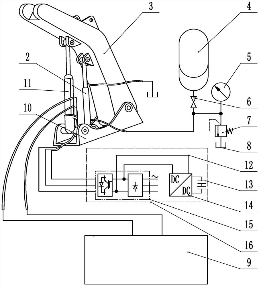
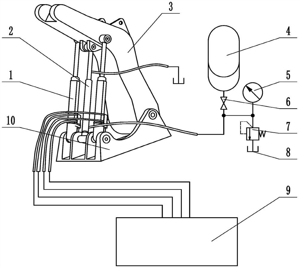
[0048] Such as Figure 6-7 As shown, an energy storage lifting system driven by a hydraulic-electric hybrid drive includes a hydraulic circuit, an electrical circuit, two electro-hydraulic mechanical cylinders, a hydraulic-pneumatic composite energy storage cylinder, a boom, a hydraulic accumulator, a pressure gauge, a cut-off valve, relief valve, fuel tank and upper frame. The electrical circuit includes: a direct current bus, at least one supercapacitor bank, a bidirectional DC-DC converter and a frequency converter.

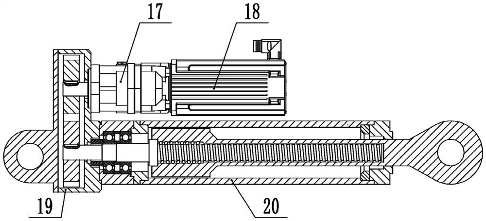
[0049] Such as figure 2 As shown, the electro-hydraulic mechanical cylinder includes the first variable pump / motor, electric motor, the first transmission box and the first mechanical cylinder; the first variable pump / motor is mechanically connected to the electric motor, and the output shaft of the first variable pump / motor It is mechanically connected coaxially with the input end of the first transmission box, and the output end of the first transmission ...


PUM


Abstract

The invention discloses an energy storage lifting system driven by a hydraulic-electric hybrid drive, which comprises at least one electro-hydraulic mechanical cylinder, at least one hydraulic-pneumatic composite energy storage cylinder, a hydraulic accumulator, a fuel tank, a stop valve, an overflow valve, and a pressure gauge , the upper frame and the boom, the system adopts the electro-hydraulic mechanical cylinder as the main driving cylinder, and uses the hydraulic-pneumatic composite energy storage cylinder and the hydraulic accumulator to balance the gravity of the boom, so that when the boom is lowered, its gravitational potential energy can be directly converted into Hydraulic and electrical energy storage. The energy storage lifting system disclosed by the invention has the advantages of high potential energy storage utilization rate of the boom, high power density, energy saving and environmental protection.

Description

technical field [0001] The invention belongs to the technical field of hydraulic systems, and in particular relates to an energy storage lifting system driven by a hydraulic-electric hybrid drive. Background technique [0002] At present, during the working process of widely used construction machinery such as excavators and loaders, due to the harsh working environment and frequent load changes, the energy utilization rate of the whole machine is low. Moreover, when these equipments are working, the boom is frequently raised and lowered under the drive of the hydraulic system. Due to the heavy weight of the boom, when the hydraulic system drives it up, the hydraulic system needs to overcome its gravity to consume energy; The potential energy of the arm is usually converted into hydraulic energy and then dissipated through the control valve into micro heat energy. This not only wastes energy, but also increases the oil temperature of the hydraulic system, which reduces the r...

Claims


Application Information

Patent Timeline
Patent Type & Authority Patents(China)
IPC IPC(8): E02F3/42E02F3/43
CPCE02F3/42E02F3/43
Inventor 权龙张凯波葛磊王君王波李泽鹏
Owner TAIYUAN UNIV OF TECH
Why Eureka
Try Eureka