Electromagnetic separation reduction machine

An electromagnetic separation and reducer technology, applied in mechanical equipment, transmission parts, gear transmission and other directions, can solve the problems of high noise, poor accuracy, complex structure of the reducer, etc., achieve ultra-low noise, liberate manpower, and simple structure Effect

Inactive Publication Date: 2018-10-19
SHAANXI UNIV OF SCI & TECH
View PDF10 Cites 0 Cited by
  • Summary
  • Abstract
  • Description
  • Claims
  • Application Information

AI Technical Summary

Problems solved by technology

[0003] The purpose of the present invention is to provide an electromagnetic separation reducer, which solves the problems of complex structure, poor precision and high noise of the reducer in the prior art

Method used


Image

  • Electromagnetic separation reduction machine
  • Electromagnetic separation reduction machine
  • Electromagnetic separation reduction machine

Examples


Embodiment Construction

[0027] The present invention will be described in detail below in conjunction with the accompanying drawings and specific embodiments.

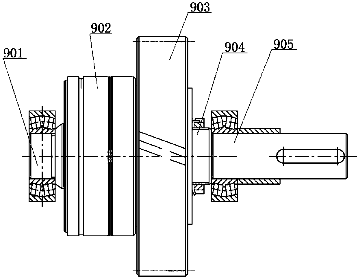
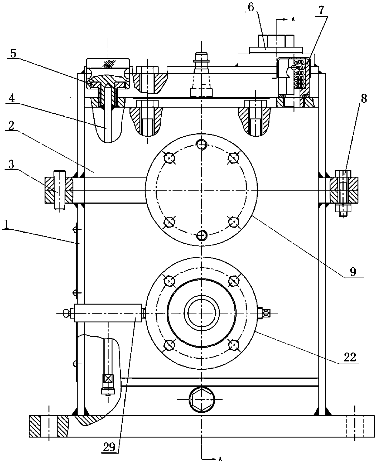
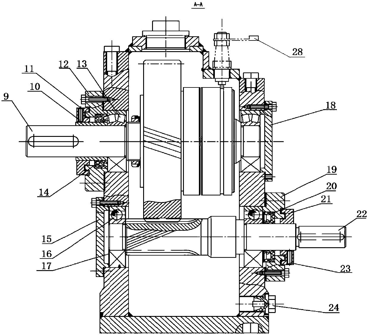
[0028] The electromagnetic separation reducer of the present invention has a structure such as Figure 1 to Figure 6 As shown, it includes a housing 1 and an upper cover 2, one side of the housing 1 and the upper cover 2 is fixedly connected by a bolt 8, and the other side of the housing 1 and the upper cover 2 is connected by a push pin 3, and the housing 1 is provided with The output shaft clutch assembly 9 and the input shaft 22 are parallel to each other, the input shaft 22 is located below the output shaft clutch assembly 9, the output shaft clutch assembly 9 includes an output shaft 904, and an electromagnetic clutch 902 and a driven gear 903 are sleeved on the output shaft 904 , the end of the output shaft 904 close to the electromagnetic clutch 902 is sleeved with a journal 901, the end of the output shaft 904 close to the driven gear...


PUM


Abstract

The invention discloses an electromagnetic separation reduction machine comprising a housing and an upper cover. The housing is fixedly connected with one side of the upper cover by bolts, and the housing is connected with the other side of the upper cover by a push pin. The housing is provided with an output shaft clutch assembly and an input shaft that are parallel to each other, and the input shaft is located below the output shaft clutch assembly. The output shaft clutch assembly comprises an output shaft, the output shaft is sleeved with an electromagnetic clutch and a driven gear. One end of the output shaft close to the electromagnetic clutch is sleeved with a journal, and one end of the output shaft close to the driven gear is connected with a shaft head through a collar. The inputshaft comprises a stepped shaft that is formed by sequentially connecting an input shaft head, a shaft body and an input shaft journal, and the other side of the shaft body adjacent to the input shaft journal is sleeved with a driving gear. The driving gear and the driven gear are engaged with each other. One end of the shaft body close to the driving gear is connected with an input shaft journal, and the shaft body and the input shaft journal are respectively fixed on two opposite sidewalls of the housing.

Description

technical field [0001] The invention belongs to the technical field of reducers, and relates to an electromagnetic separation reducer. Background technique [0002] The reducer is the most common component in various mechanical equipment. Its main function is to reduce or increase the speed of the motor to the required speed of the mechanical equipment. However, most of the commonly used reducers can meet the requirements of deceleration during the deceleration process, but When the reducer is disconnected from the power supply, the huge torque makes it continue to rotate in the original direction of motion, and cannot achieve a fast stop. It also causes motion deviation in some mechanisms or precision motion instruments. In order to make it stop quickly and achieve precise positioning The purpose is to design the electromagnetic separation reducer so that it can absorb the friction plate under the magnetic force to make it stop quickly and accurately. At the same time, the...

Claims


Application Information

Patent Timeline
Patent Type & Authority Applications(China)
IPC IPC(8): F16H1/06F16H57/023F16H57/021F16H57/028F16C3/02
CPCF16C3/02F16H1/06F16H57/021F16H57/023F16H57/028
Inventor 栾飞田帅博桓源兰建斌王凯航付韦虎贺阳方文平
Owner SHAANXI UNIV OF SCI & TECH
Why Eureka
Try Eureka