Online monitoring system for fault location of transmission line

A technology of fault location and monitoring system, applied in fault location, information technology support system, fault detection according to conductor type, etc., can solve the problem that the controller is prone to crash.

Pending Publication Date: 2018-10-19
CHONGQING LINIAN TEACHING INSTR
View PDF2 Cites 6 Cited by
  • Summary
  • Abstract
  • Description
  • Claims
  • Application Information

AI Technical Summary

Problems solved by technology

[0006] The present invention provides an on-line monitoring system for transmission line fault location, which solves the phenomenon that the control

Method used


Image

  • Online monitoring system for fault location of transmission line
  • Online monitoring system for fault location of transmission line
  • Online monitoring system for fault location of transmission line

Examples


Embodiment Construction

[0025] In order to make the technical means, creative features, goals and functions achieved by the present invention clearer and easier to understand, the present invention will be further elaborated below in conjunction with the accompanying drawings and specific embodiments:

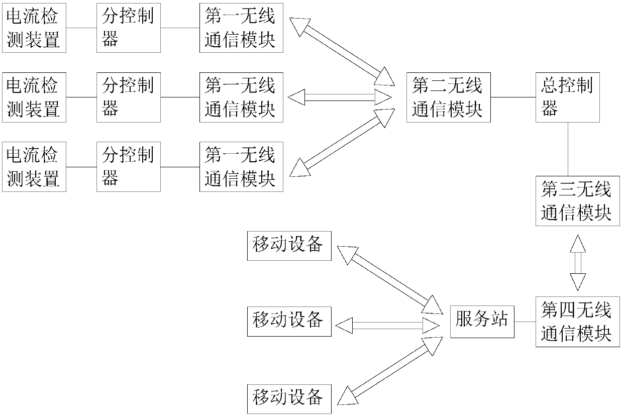
[0026] Such as figure 1 As shown, this embodiment proposes an online monitoring system for transmission line fault location, including:

[0027] A plurality of current detection devices, at least three detection points are arranged between two adjacent substations, each detection point is equipped with a current detection device, and each current detection device is used to detect the current output value of the detection point;

[0028] Sub-controller, each current detection device is connected to a sub-controller, the sub-controller is used to judge whether the received current output value exceeds the threshold value and when the current output value of a current detection device between two adjace...


PUM


Abstract

The invention provides an online monitoring system for fault location of a transmission line, comprising: a plurality of current detecting devices, wherein at least three detection points are arrangedbetween two adjacent substations, and each detection point is provided with a current detecting device; sub-controllers, wherein each of the current detecting devices is connected to one sub-controller; a first wireless communication modules, wherein each sub-controller is connected to the first wireless communication module; a second wireless communication module, wherein the first wireless communication module is connected to the second wireless communication module; and a total controller, wherein the second wireless communication module is connected to the total controller, and the totalcontroller calculates a fault point position according to the detection data of each current detecting device. The online monitoring system for fault location of the transmission line solves the phenomenon in the prior art that the controller is prone to crash when one controller executes the fault occurrence judgment and the fault location finding at the same time.

Description

technical field [0001] The invention relates to transmission line fault detection, in particular to an on-line monitoring system for transmission line fault location. Background technique [0002] A Chinese patent discloses a transmission line fault location system with the application number CN201520275841.3. The transmission line fault location system includes: a sampling device connected to the transmission line; a data acquisition device connected to the sampling device; a fault starting device connected to the data acquisition device ; The wireless transmission device is connected to the fault starting device; the power supply device is connected to the transmission line, the data acquisition device, the fault starting device and the wireless transmission device; The time difference between the first fault waveform and the second fault waveform collected by the device, the transmission speed of the traveling wave in the transmission line, and the distance between the sa...

Claims


Application Information

Patent Timeline
IPC IPC(8): G01R31/08
CPCG01R31/085Y04S10/52
Inventor 王平杨飞杨宇帆白云王林泓
Owner CHONGQING LINIAN TEACHING INSTR
Why Eureka
Try Eureka