A method to achieve cross-scale lithography or multi-resolution imaging by changing the beam expansion ratio

A multi-resolution, cross-scale technology, applied in the direction of microlithography exposure equipment, optics, optical components, etc., can solve problems such as alignment errors, and achieve the effect of simple operation, fast speed and high precision

Active Publication Date: 2019-08-13
SHANGHAI INST OF OPTICS & FINE MECHANICS CHINESE ACAD OF SCI
View PDF7 Cites 0 Cited by
  • Summary
  • Abstract
  • Description
  • Claims
  • Application Information

AI Technical Summary

Problems solved by technology

[0003] Zone plates and photonic sieves have important applications in the fields of X-rays, extreme ultraviolet imaging and focusing, but their sizes are distributed in the range of nanometers to micrometers when they are manufactured, and the alignment error problem described above will occur when using traditional processes ; The manufacture of chips is promoting the development of information technology, but the manufacturing process also faces the above problems

Method used


Image

  • A method to achieve cross-scale lithography or multi-resolution imaging by changing the beam expansion ratio
  • A method to achieve cross-scale lithography or multi-resolution imaging by changing the beam expansion ratio
  • A method to achieve cross-scale lithography or multi-resolution imaging by changing the beam expansion ratio

Examples


Embodiment 1

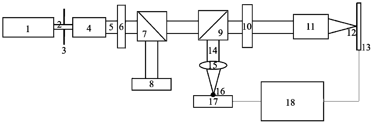
[0031] The present invention realizes the method of cross-scale lithography or multi-resolution imaging by changing the ratio of beam expansion. The single-beam point scanning lithography or imaging system sequentially includes a diaphragm 2, a beam expander, and a half-wave plate 6 along the output direction of the optical path. , beam splitter 7, polarization beam splitter 9, quarter wave plate 10 and objective lens 11, its steps include:

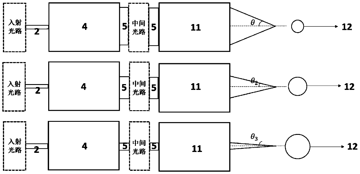
[0032] 1) Replace the beam expander with an electric adjustable magnification beam expander 4, whose magnification is continuously adjustable from 1 to 64 times;

[0033] 2) Adjust the magnification of the electrically adjustable magnification beam expander 4 to m times, so that the beam 5 after the beam expansion is identical to the diameter of the entrance pupil of the objective lens 11;

[0034] 3) according to formula D=1.22λ / NA, calculate the diameter D of focus light spot 12 after light beam 5 passes through objective lens 11 in the...


PUM

PropertyMeasurementUnit
diameteraaaaaaaaaa
diameteraaaaaaaaaa

Abstract

The invention discloses a method for achieving cross-scale photolithography or multi-resolution imaging through change of a beam expansion ratio. A beam expanding mirror in a single-beam spot scanningphotolithography or imaging system is replaced with an electric adjustable magnification beam expanding mirror, and then according to a relevant calculation formula, continuous adjustability of the diameters of focal spots is achieved through adjustment of the beam expansion ratio. According to the method, the spots with the continuously adjustable diameters can be provided in the single-beam spot scanning photolithography or imaging system, and the cross-scale photolithography or multi-resolution optical imaging can be achieved rapidly, simply and conveniently.

Description

technical field [0001] The invention relates to photolithography and optical imaging, in particular to a method for realizing cross-scale photolithography or multi-resolution imaging by changing the beam expansion ratio. Background technique [0002] Laser lithography and optical imaging are the core technologies of integrated circuit and micro-optical components manufacturing and bio-life medicine. The lithography or imaging system based on point scanning focuses the incident parallel light into a diffraction-limited spot, and completes the writing or Optical imaging, so its writing size or optical imaging resolution is determined by the size of the focused spot. Due to the different line widths on integrated circuits and micro-optical components, in actual production, it is necessary to replace the lens to obtain focused spots of different sizes, and use graphic splicing technology for distributed writing. When the lens is replaced during the process, the platform moves af...

Claims


Application Information

Patent Timeline
Patent Type & Authority Patents(China)
IPC IPC(8): G03F7/20G02B27/09
CPCG02B27/0938G03F7/20G03F7/70091G03F7/70216
Inventor 魏劲松丁晨良王正伟
Owner SHANGHAI INST OF OPTICS & FINE MECHANICS CHINESE ACAD OF SCI
Why Eureka
Try Eureka