Time domain-based spectrum detection system

A spectral detection and time-domain technology, applied in the direction of testing optical properties, etc., to achieve the effect of spectral detection

Inactive Publication Date: 2012-05-09
UNIV OF ELECTRONICS SCI & TECH OF CHINA
View PDF7 Cites 9 Cited by
  • Summary
  • Abstract
  • Description
  • Claims
  • Application Information

AI Technical Summary

Problems solved by technology

Systems based on frequency domain implementation cannot perform spectral detection on serially multiplexed F-P interferometers and other optical devices under test

Method used


Image

  • Time domain-based spectrum detection system
  • Time domain-based spectrum detection system
  • Time domain-based spectrum detection system

Examples


Embodiment 1

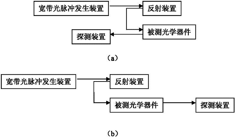
[0021] like image 3 As shown, the system includes a broadband optical pulse generating device, a circulator, a reflecting device, an optical device under test, and a detecting device. The circulator of this embodiment is a four-port circulator.

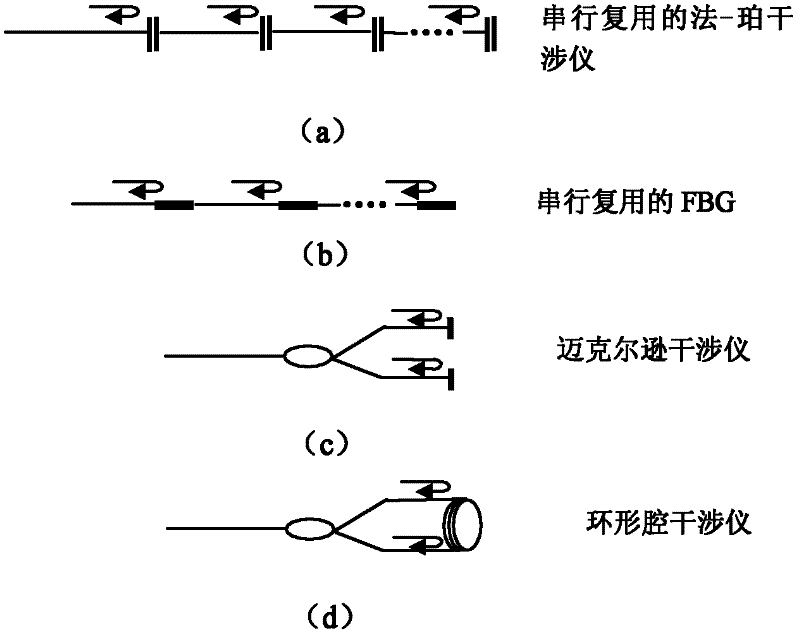
[0022] The broadband optical pulse generating device provides optical energy input for the entire detection system, and the broadband optical pulse generated by the broadband optical pulse generating device is connected to port 1 of the circulator, and port 2 of the circulator is connected to the reflection device. This example uses FBG with high reflectivity as the reflection unit, and the reflection device consists of n reflection units (R 1 , R 2 , R 3 ,...,R n ) in series. The value of n is determined by the wavelength resolution of the spectral detection actually required. The larger n is, the smaller the wavelength interval is, and the higher the resolution of the wavelength in the detected spectral features is, the FBG c...

Embodiment 2

[0024] like Figure 4 As shown, the system includes a broadband optical pulse generating device, a circulator, an optical device under test, a reflecting device, and a detecting device.

[0025] The broadband optical pulse generating device provides optical energy input for the entire detection system, and the broadband optical pulse generated by the broadband optical pulse generating device is connected to port 1 of the circulator, and port 2 of the circulator is connected to the reflection device. The reflection device of this example is composed of a wavelength division multiplexer (WDM) and n reflectors with different distances from the wavelength division multiplexer. The mirror reflects back to the wavelength division multiplexer, and the wavelength division multiplexer outputs optical pulse trains corresponding to light intensities of different wavelengths at different positions in the time domain. The distance between each reflector and the wavelength division multipl...

Embodiment 3

[0027] like Figure 5 As shown, the system includes a broadband optical pulse generating device, a beam splitter, N groups of circulators, an optical device under test, a reflecting device and a detecting device, where N is a positive integer greater than or equal to 2. In implementation, four-port or even more port number circulators, three-port circulators, or fiber couplers can be used to complete the optical transmission between the broadband optical pulse generation device, the optical device under test, the reflection device and the detection device . At present, the commonly used circulator is a three-port circulator. When the optical device under test is a reflective device, two three-port circulators are needed to complete the detection of a group of optical devices under test. For example, when detecting the optical device 1 under test, the circulator 1 and the circulator 2 are used to transmit optical signals. The output end of the beam splitter is connected to th...


PUM


Abstract

The invention provides a time domain-based spectrum detection system, which can be used for performing spectrum detection on a serial multiplex detected optical device. In the detection system, a reflection device comprises n reflection units at different spatial positions; each reflection unit is used for reflecting optical pulses of different wavelengths; n is an integer of over 2; broadband optical pulses generated by a broadband optical pulse generating device are transmitted to the reflection device; the reflection device is used for reflecting the received broadband optical pulses by using the reflection units at different positions to form optical pulse strings which correspond to the optical intensity of different wavelengths at different positions on a time domain; and a detection device is used for detecting the optical intensity of each pulse in the optical pulse strings which are reflected or transmitted by the detected optical device to obtain a spectrum of the detected optical device. In the system provided by the invention, discrete optical pulse strings on the time domain formed by the broadband optical pulses reflected by the reflection device enter the detected optical device, so that the spectrum information of the detected optical device can be distinguished on the time domain.

Description

technical field [0001] The invention relates to optical fiber measurement technology. technical background [0002] The spectral characteristic is one of the important parameters reflecting the optical instrument. In the prior art, the spectral detection is all realized in the frequency domain. In the existing spectral detection system, the broadband continuous light hits the spectroscopic dispersive element, and the spectroscopic dispersive element moves at each wavelength. The detector distinguishes the spectral features according to the energy difference of the continuous light at each wavelength. The system implemented based on the frequency domain cannot detect the spectrum of the optical device under test such as the serial multiplexed F-P interferometer. Contents of the invention [0003] The technical problem to be solved by the present invention is to provide a spectral detection system based on time domain, which can perform spectral detection on serially multip...

Claims


Application Information

Patent Timeline
Patent Type & Authority Applications(China)
IPC IPC(8): G01M11/02
Inventor 冉曾令倪敏
Owner UNIV OF ELECTRONICS SCI & TECH OF CHINA
Why Eureka
Try Eureka