Airborne thinned array antenna downward-looking three-dimensional imaging radar system and imaging method

A sparse array and three-dimensional imaging technology, which is applied in the radio wave measurement system, radio wave reflection/re-radiation, and re-radiation, can solve the problems of limited observation width, narrow sub-array beam, and increased number of sub-arrays. Achieve high-precision motion compensation, realize motion compensation, and improve the effect of imaging quality

Active Publication Date: 2013-11-13
INST OF ELECTRONICS CHINESE ACAD OF SCI
View PDF4 Cites 9 Cited by
  • Summary
  • Abstract
  • Description
  • Claims
  • Application Information

AI Technical Summary

Problems solved by technology

[0008] The technical problem to be solved by the present invention is that there are two deficiencies in the existing airborne array antenna downward looking three-dimensional imaging radar system: one, if the cross-track array antenna is composed of small-sized sub-arrays, its beam width is wider, so A larger observation width can be obtained, but the size of the sub-array is small, the number of required sub-arrays will increase sharply, and the complexity of the system will be incre

Method used


Image

  • Airborne thinned array antenna downward-looking three-dimensional imaging radar system and imaging method
  • Airborne thinned array antenna downward-looking three-dimensional imaging radar system and imaging method
  • Airborne thinned array antenna downward-looking three-dimensional imaging radar system and imaging method

Examples


Example Embodiment

[0041] In order to make the objectives, technical solutions and advantages of the present invention clearer, the present invention will be further described in detail below in conjunction with specific embodiments and with reference to the accompanying drawings.

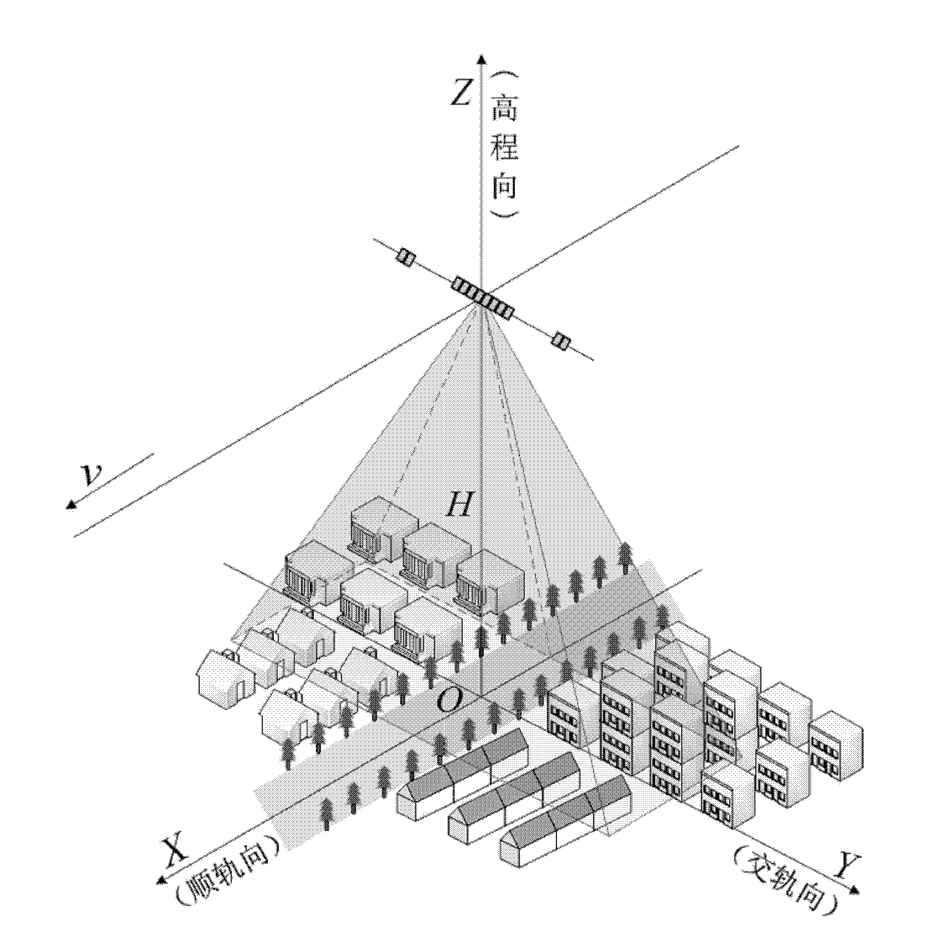
[0042] For such as figure 1 The airborne downward-looking three-dimensional imaging radar system shown in the present invention is designed from the perspective of analyzing the array layout form of its orbiting direction, so as to realize high-resolution wide-range imaging of the observation scene.

[0043] Specifically, the airborne sparse array down-view three-dimensional imaging radar system of the present invention includes an airborne platform, a sparse array antenna system, and a distributed POS (Position and Orientation System).
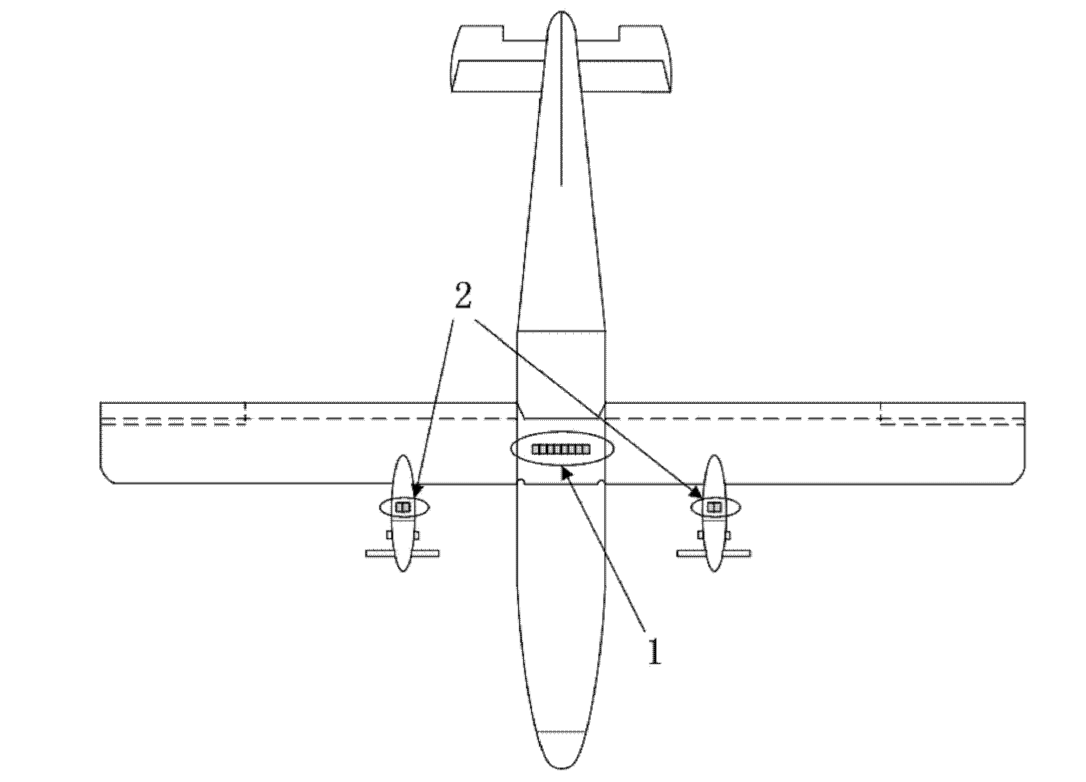
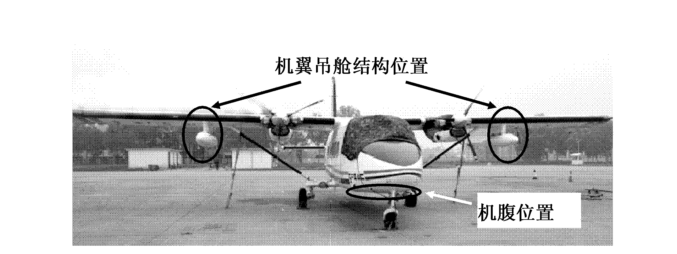
[0044] The carrier platform is an aircraft for carrying the sparse array antenna system and distributed POS. The aircraft can be equipped with array antennas in the middle and both sides, a...


PUM


Abstract

The invention discloses an airborne thinned array antenna downward-looking three-dimensional imaging radar system and imaging method. The airborne thinned array antenna downward-looking three-dimensional imaging radar system comprises an aerial carrier platform, a thinned array antenna system and a distributed position and orientation system (POS). The aerial carrier platform is used for carrying the thinned array antenna system and the distributed POS, and array antennae can be distributed in the middle and on two sides of an aircraft. The thinned array antenna system is composed of a plurality of densely distributed sub arrays arranged in the middle and one or two sub arrays located on two sides. Accurate measuring of the multi-phase center relative space position of the array antennae can be achieved through the distributed POS. In the direct downward-looking mode, the observation width is broadened through a scanning mode which combines a Scan SAR mode and a Sweep SAR mode. When the aerial carrier operates in the upper air, a cross rail direction equivalent array can be obtained in a thinned re-navigation mode with Barker codes serving as the sampling criterion, and the cross rail direction resolution is improved. The array antennae in space thinned distribution are adopted in the cross rail direction of the aerial carrier and high-resolution wide-width three-dimensional imaging of the observation scenes is achieved.

Description

technical field [0001] The invention relates to the technical field of radar systems, information acquisition and processing, in particular to an airborne sparse array antenna downward-looking three-dimensional imaging radar capable of realizing high-resolution and wide-width three-dimensional imaging. Background technique [0002] The airborne downward-looking 3D imaging radar system is a new microwave 3D imaging radar system. Its imaging principle is as follows: figure 1 shown. Through the movement of the carrier platform, a synthetic aperture is formed in the X direction (following the track direction), and the along-track resolution is obtained; an array antenna is used to form a real aperture in the Y direction (cross-track direction), and the cross-track resolution is obtained; The broadband signal is transmitted in the direction (elevation direction), and the range (elevation direction) resolution is obtained through pulse compression processing, so as to realize the...

Claims


Application Information

Patent Timeline
IPC IPC(8): G01S13/90G01S7/02
Inventor 李道京滕秀敏
Owner INST OF ELECTRONICS CHINESE ACAD OF SCI
Why Eureka
Try Eureka