
A csar ground moving target refocusing imaging method

A technology of ground moving target and imaging method, applied in the field of synthetic aperture radar ground moving target indication, can solve the problems of complex azimuth and distance coupling, increasing the difficulty of refocusing imaging, and difficult to accurately obtain motion parameter information, etc.

Active Publication Date: 2020-09-18
NAT UNIV OF DEFENSE TECH
View PDF6 Cites 0 Cited by
  • Summary
  • Abstract
  • Description
  • Claims
  • Application Information

AI Technical Summary

Problems solved by technology

[0003] Ground moving targets are generally non-cooperative targets, and it is difficult to accurately obtain information about their motion parameters, which increases the difficulty of refocusing imaging
In addition, while the special motion geometry of CSAR brings the advantages of omni-directional multi-aperture angle observation, it also introduces complex azimuth and distance coupling, which makes the moving target refocusing method under traditional linear SAR invalid.

Method used


Image

  • A csar ground moving target refocusing imaging method
  • A csar ground moving target refocusing imaging method
  • A csar ground moving target refocusing imaging method

Examples


Embodiment Construction

[0084] In order to make the object, technical solution and advantages of the present invention clearer, the implementation manner of the present invention will be further described in detail below in conjunction with the accompanying drawings.

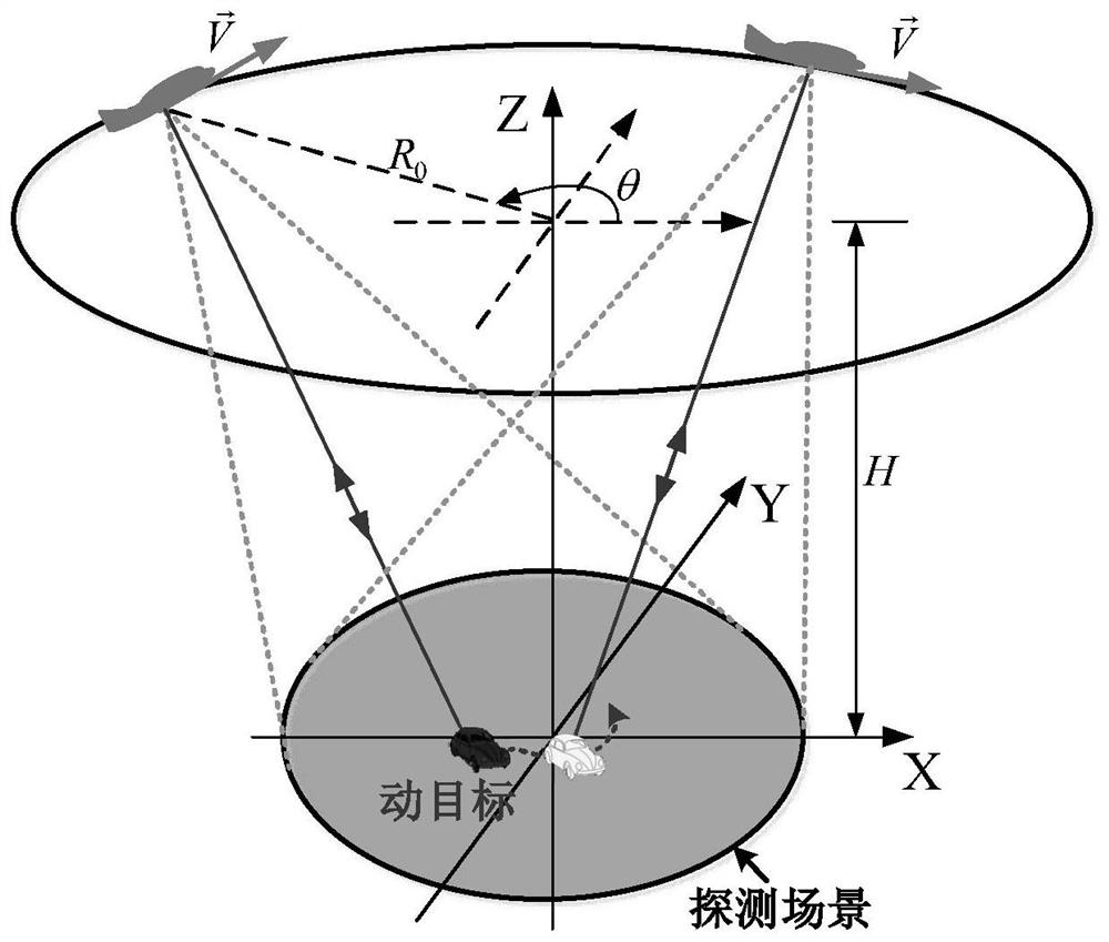
[0085] figure 1 It is a schematic diagram of the application scene of the present invention, in which the radar platform flies along a circle at a speed of The beam is always pointed to the detection area, and the moving target (car) in the detection area is observed for a long time.

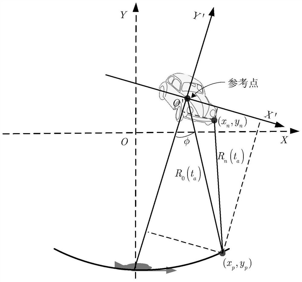
[0086] figure 2 It is a schematic diagram of the observation geometry under the sub-aperture, and a scattering point of a moving target is selected as a reference point for motion compensation.

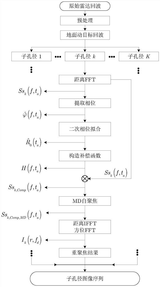
[0087] image 3 It is a flowchart of the present invention. A ground moving target refocusing method suitable for CSAR, comprising the following steps:

[0088] S1. Receive the radar echo signal of the moving target and perform preprocessing. Preprocessi...


PUM


Abstract

The invention belongs to the field of synthetic aperture radar (SAR) ground moving target indication, and relates to a curve SAR (CSAR) ground moving target refocusing imaging method. The method comprises the following steps: S1, receiving a radar echo signal of a moving target, and preprocessing the radar echo signal; S2, dividing the radar echo signal into a plurality of sub-aperture echo signals along the azimuth direction; S3, transforming the sub-aperture echo signals into a distance frequency domain, and extracting phases of the signals along the azimuth direction one frequency point after another; S4, calculating a distance estimated value according to the extracted phases, and constructing a phase compensation factor by quadratic curve fitting; S5, performing motion compensation bythe phase compensation factor; S6, compensating for a phase estimation error by a map-drift (MD) self-focusing method; S7, performing Fourier transform along the azimuth direction and performing inverse Fourier transform along the distance direction respectively to obtain a moving target re-focusing result under a current sub-aperture; and S8, repeating the steps S3 to S7 to obtain a moving target re-focusing image sequence under a plurality of sub-apertures. Through adoption of the method, motion compensation is realized under the situation that target motion parameters are unknown.

Description

technical field [0001] The invention belongs to the field of ground moving target indication (GMTI) of synthetic aperture radar (Synthetic Aperture Radar, SAR), and relates to a ground moving target refocusing (Ground Moving Target Indication) suitable for curve synthetic aperture radar (Curve SAR, CSAR). Moving Target Refocusing, GMTR) imaging method. Background technique [0002] Synthetic Aperture Radar (SAR) is a radar technology that can perform high-resolution microwave imaging on the observation scene. CSAR is a new SAR imaging system, that is, the radar platform makes a large curve or wide-angle arc around the observation scene. A radar system whose beam is always pointing to the target scene for observation and imaging. CSAR can achieve sub-wavelength resolution of stationary targets on the ground, and can observe targets from multiple angles in all directions to obtain more detailed target azimuth scattering information. In order to improve battlefield awareness,...

Claims


Application Information

Patent Timeline
Patent Type & Authority Patents(China)
IPC IPC(8): G01S13/90
Inventor 安道祥王武陈乐平罗雨潇范崇祎周智敏
Owner NAT UNIV OF DEFENSE TECH
Learn More