
Image processing method and apparatus, and image forming apparatus

a technology of image processing and forming apparatus, applied in the direction of electrical apparatus, printing, pictoral communication, etc., can solve the problems of method of using no technology is known for controlling the overlap of a plurality of inks, so as to achieve both image resolution and tonal gradation

Inactive Publication Date: 2005-10-06
FUJIFILM CORP
View PDF2 Cites 9 Cited by
  • Summary
  • Abstract
  • Description
  • Claims
  • Application Information

AI Technical Summary

Benefits of technology

[0013] Preferably, the first ink component is an ink component of the color having a strongest visual impact. Accordingly, by specifying the dot arrangement firstly for the color having the strongest visual impact, it is possible to achieve the most desirable arrangement of the dots of the color having the strongest visual impact.
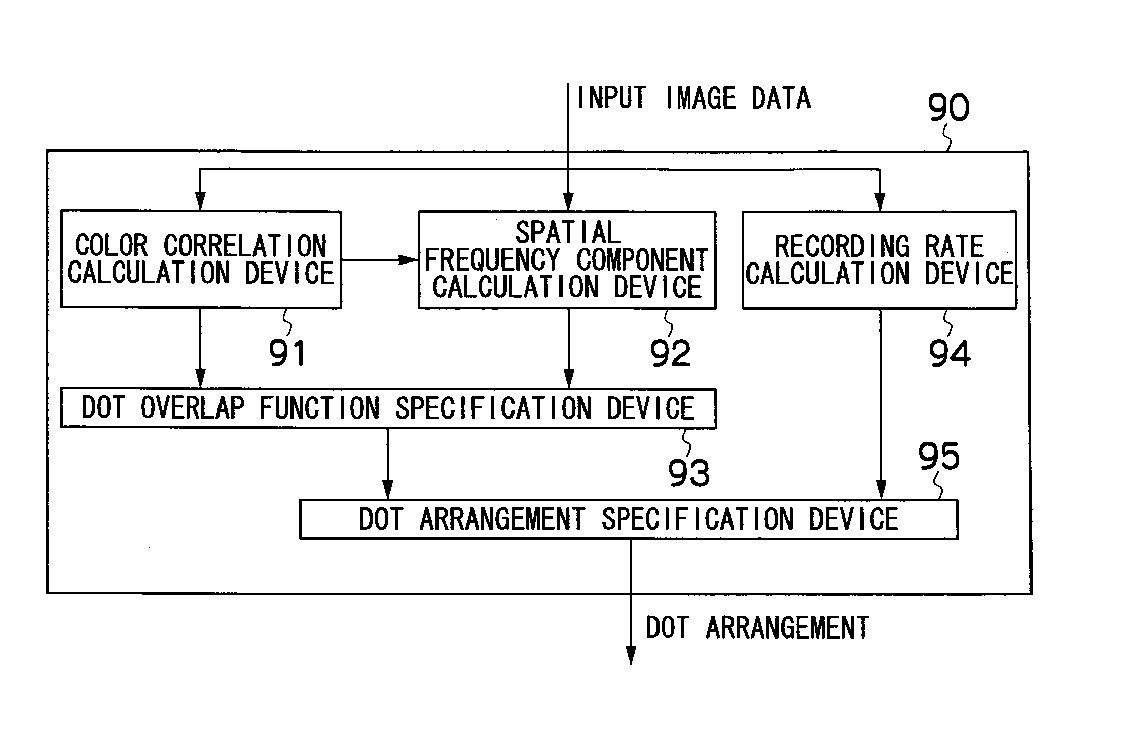
[0033] According to the image processing method and image processing apparatus according to the present invention, and the image forming apparatus comprising same, as described above, it is possible to achieve both image resolution and tonal gradation by controlling ink overlap (dot overlap) for a plurality of inks, according to the spatial frequency component and the color correlation of the original image.

Problems solved by technology

However, Japanese Patent Application Publication No. 8-214159 provides no disclosure at all regarding methods for using a plurality of inks.
However, in the method described in Japanese Patent Application Publication No. 8-214159, there is no disclosure regarding use of a plurality of inks and although overlapping between a plurality of inks is controlled in conventional half-toning technology in order to improve color reproduction and granularity, no technology is currently known for controlling overlapping between a plurality of inks with the object of achieving compatibility of image resolution and tonal gradation.

Method used


Image

  • Image processing method and apparatus, and image forming apparatus
  • Image processing method and apparatus, and image forming apparatus
  • Image processing method and apparatus, and image forming apparatus

Examples


first embodiment

[0142] Next, the action of the first embodiment is described in accordance with the flowchart shown in FIG. 11A.

[0143] Firstly, at step S100 in FIG. 11A, the input image data is read into the image memory 74 via the communications interface 70, and is stored temporarily, after which it is subsequently called up from the image memory 74 by the system controller 72 and inputted to the image processing unit 90. When the input image data is inputted to the image processing unit 90, it is supplied respectively to the color correlation calculation device 91, the spatial frequency component calculation device 92 and the recording rate calculation device 94. The input image is divided up into a number of regions (blocks) for calculation purposes, and the following processing is carried out respectively for each block.

[0144] Next, at step S110, the color correlation calculation device 91 calculates the color correlation and the spatial frequency component calculation device 92 calculates th...

second embodiment

[0163] Next, a second embodiment is described.

[0164]FIG. 15 is a block diagram showing the approximate composition of an image processing unit 190 according to a second embodiment. As shown in FIG. 15, the image processing unit 190 of the present embodiment is constituted by a color correlation calculation device 191, a spatial frequency component calculation device 192, a threshold value matrix specification device 193, a recording rate calculation device 194, and a dot arrangement specification device 195.

[0165] The difference between this embodiment and the first embodiment described above lies in the fact that the threshold value matrix specification device 193 is provided instead of the dot overlap function specification device 93. In other words, the present embodiment decides the dot arrangement by using a threshold value matrix.

[0166] In the image processing unit 190 of the present embodiment, the color correlation calculation device 191, the spatial frequency component ca...

third embodiment

[0181] Next, the present invention will be described.

[0182]FIG. 20 is a block diagram showing the approximate composition of an image processing unit according to a third embodiment. As shown in FIG. 20, the image processing unit 290 of the present embodiment is constituted by a spatial coordinate calculation device 291, a spatial frequency component calculation device 292, a dot overlap function specification device 293, a recording rate calculation device 294, and a dot arrangement specification device 295.

[0183] The present embodiment comprises a color space coordinate calculation device 291 instead of the color correlation calculation device 91 according to the first embodiment described above, and it specifies a dot overlap function according to the color space coordinates (L, a, b), rather than the color correlation.

[0184] The color space coordinate calculation device 291 converts the input RGB image data into color space coordinates (L, a, b) by means of a commonly known me...


PUM


Abstract

The image processing method for specifying dot arrangements for respective ink components according to image data, when forming an image on a recording medium by means of dots of inks of n colors, where n is any positive integer, the method comprises the steps of: calculating color correlation and spatial frequency components from the image data; specifying a dot overlap function for controlling overlapping between dots of the ink components, according to the calculated color correlation and spatial frequency components; calculating an ink recording rate of each of the inks from the image data; specifying the dot arrangement of a first ink component by means of a prescribed method, according to the ink recording rate; and determining a dot arrangement for the inks of the n colors, in such a manner that, taking k to be an integer where 2≦k≦n, the dot arrangement of the kth ink component is specified according to the ink recording rate of the kth ink component, and the previously specified dot arrangement and dot overlap function of the first ink component through to the (k−1)th ink component.

Description

BACKGROUND OF THE INVENTION [0001] 1. Field of the Invention [0002] The present invention relates to an image processing method and image processing apparatus, and to an image forming apparatus comprising same, and more particularly, to an image processing method and image processing apparatus, and an image forming apparatus comprising same, whereby both image resolution and tonal gradation can be achieved simultaneously when forming an image by means of dots using a plurality of inks. [0003] 2. Description of the Related Art [0004] In the related art, an image forming apparatus is known in which images are formed by outputting a plurality of colors onto a recording medium by means of a coloring material, such as ink, toner, or the like. In an image forming apparatus of this kind, images are formed by means of a plurality of dots formed by means of ink, toner, or the like. Therefore, an image is reproduced according to whether or not dots are present on a recording medium, such as w...

Claims


Application Information

Patent Timeline
IPC IPC(8): B41J2/205B41J2/21H04N1/40
CPCH04N1/40087B41J2/2132
Inventor YAMAZAKI, YOSHIROU
Owner FUJIFILM CORP
Learn More