Image forming apparatus and method

a technology of image forming apparatus and head unit, which is applied in the direction of measuring apparatus components, instruments, printing, etc., can solve the problems of increasing the possibility of ink discharge problems in the head, shortening the printing time, and increasing the total number of nozzles, so as to reduce the number of head units, reduce the number of coloring materials, and reduce the number of types of coloring materials.

Inactive Publication Date: 2005-05-19
FUJIFILM CORP
View PDF10 Cites 5 Cited by
  • Summary
  • Abstract
  • Description
  • Claims
  • Application Information

AI Technical Summary

Benefits of technology

[0046] According to the present invention, it is possible to substitute recording using a high-density coloring material by means of a low-density coloring material of the same color type, for at least one of cyan and magenta, and hence the number of types of coloring materials can be reduced, whilst achieving high-quality image recording. By this means, recording elements corresponding to conventional high-density coloring materials become unnecessary, and hence the number of head units can be reduced, thus making it possible, in turn, to reduce the size and cost of the overall apparatus, to improve reliability, and the like, and to obtain prints of high quality (high resolution and high tonal graduation) equivalent to photographic quality.

Problems solved by technology

Due to improvements of these kinds, it has been possible to shorten the printing time, but on the other hand, the following types of problems have arisen.
More specifically, the increase in the number of nozzles described above leads to problems in that, in addition to raising the cost of the device, the increase in the total number of nozzles, and the fact that the total length of the flow passages inside the head for supplying ink to these respective nozzles becomes longer, give rise to an increased possibility of an ink discharge problem occurring in the head.
This is not limited to an increased probability of simple breakdowns, but rather means that there is an increased possibility of problems such as air bubbles becoming trapped inside the ink flow passages and it becoming impossible to perform normal discharge, or problems which are intrinsic to inkjet systems, such as the ink viscosity rising in the vicinity of the nozzles, and causing discharge failures.
More particularly, in a single pulse type inkjet printer, which, unlike a shuttle scan type printer for printing by scanning an inkjet head back and forth, has a fixed head of a length equal to or greater than the print image and performs printing by conveying printing paper in a direction orthogonal to the longitudinal direction of the head, the number of nozzles per ink color may exceed 10,000, and hence the issue of increased possibility of problems such as those described above is very serious indeed.
Furthermore, if inks of six colors are used in a single pass type inkjet printer, then naturally, the overall size of the head will become very large, and the cost thereof will increase.
However, ejecting droplets at different resolutions in this way is extremely complex, when it comes to carrying out image processing and determining the location of the dots.
Furthermore, if a plurality of ink droplets are simply ejected, then since there is a limit on the capacity of the paper to receive ink, this is not a practicable way of achieving high image quality.
Therefore, it does not disclose information of particularly great value with regard to reducing the number of colors (number of nozzles).

Method used


Image

  • Image forming apparatus and method
  • Image forming apparatus and method
  • Image forming apparatus and method

Examples


Embodiment Construction

General Configuration of an Inkjet Recording Apparatus (Printer)

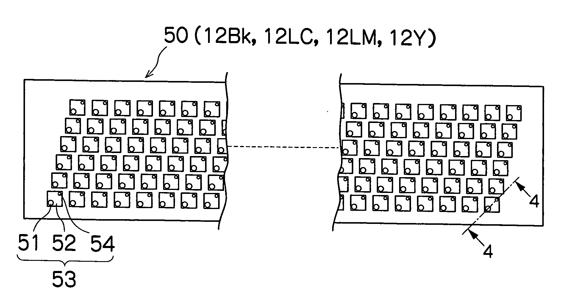
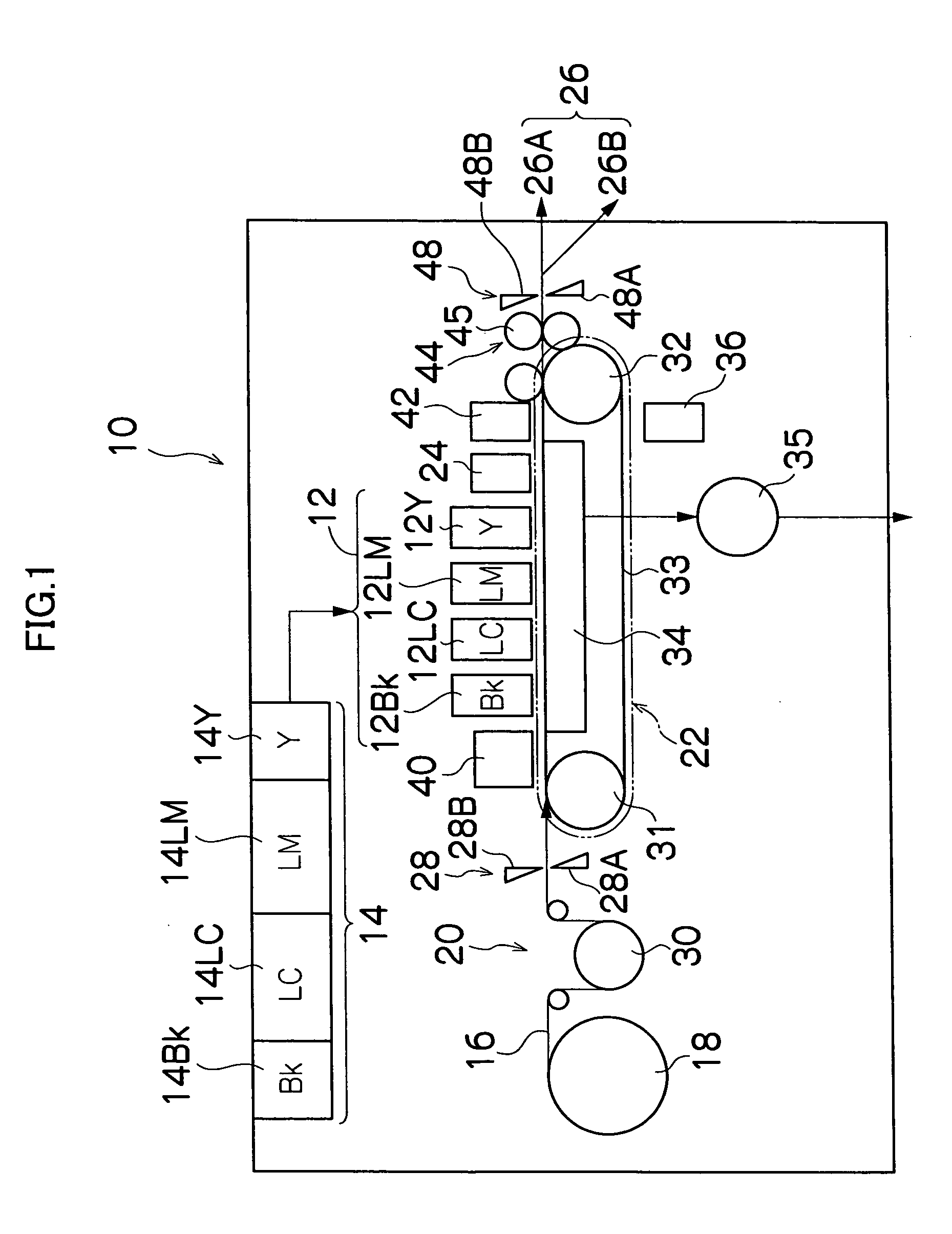
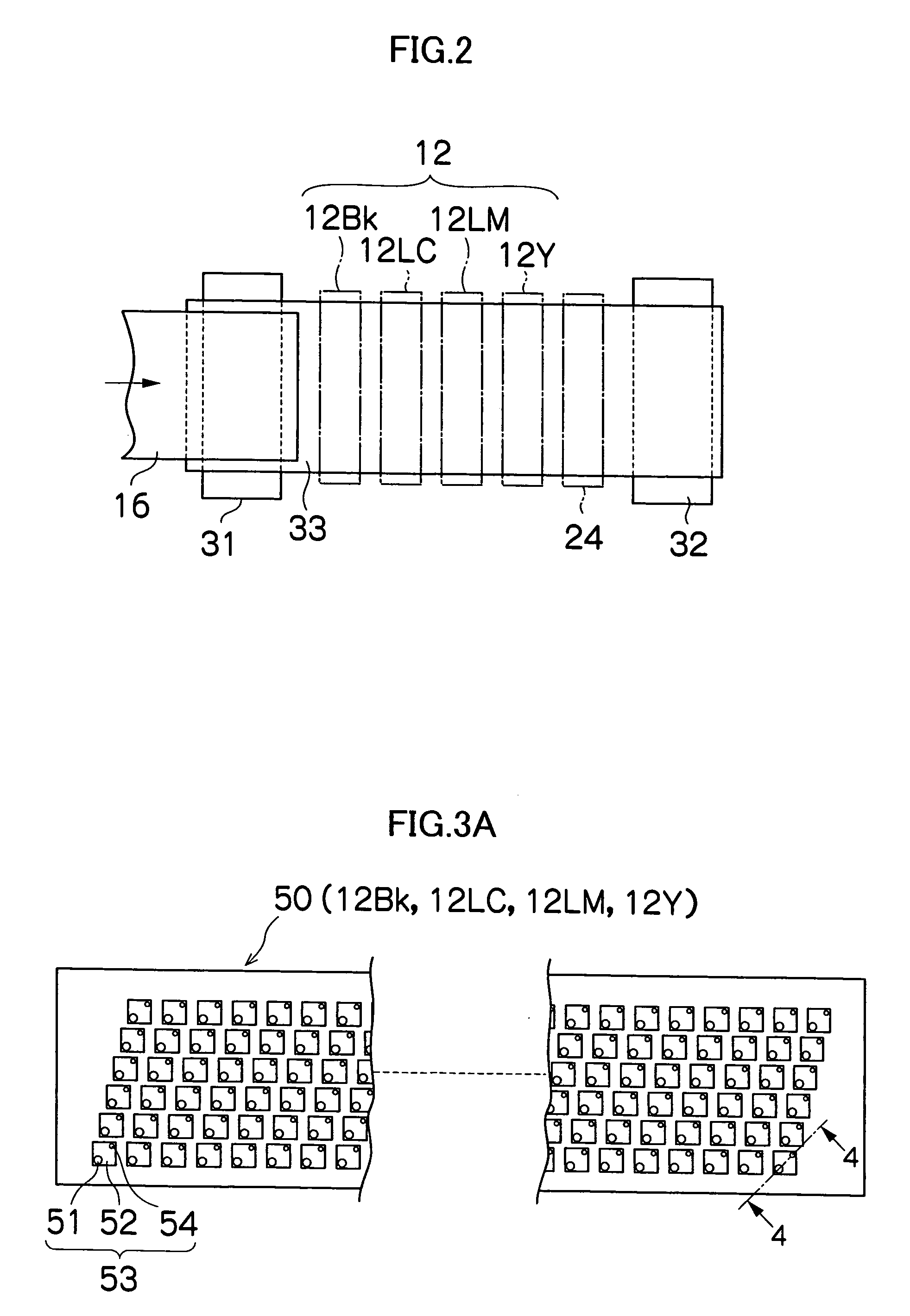
[0060]FIG. 1 is a general schematic drawing of an inkjet recording apparatus according to an embodiment of the present invention. As shown in FIG. 1, the inkjet recording apparatus 10 comprises: a printing unit 12 having a plurality of print heads 12Bk, 12LC, 12LM, and 12Y for ink colors of black (Bk), light cyan (LC), light magenta (LM), and yellow (Y), respectively; an ink storing and loading unit 14 for storing inks of Bk, LC, LM and Y to be supplied to the print heads 12Bk, 12LC, 12LM, and 12Y; a paper supply unit 18 for supplying recording paper 16; a decurling unit 20 for removing curl in the recording paper 16; a suction belt conveyance unit 22 disposed facing the nozzle face (ink-droplet ejection face) of the print unit 12, for conveying the recording paper 16 while keeping the recording paper 16 flat; a print determination unit 24 for reading the printed result produced by the printing unit 12; and a paper ou...


PUM


Abstract

The image forming apparatus forms an image on a recording medium by using coloring materials of at least three colors of cyan, magenta and yellow, wherein: at least one of the cyan and magenta color materials is a coloring material of lower density than the yellow; and ink brightness or perception of graininess on the recording medium is substantially the same for each of the three coloring materials, if recording is carried out on the recording medium according to any one condition of: a first condition wherein recording is carried out using substantially the same dot size for each color, at a recording rate of 100%; a second condition wherein recording is carried out using substantially the same dot size for each color, at the same recording rate for each color with respect to the surface area of the recording medium that is to be evaluated, and at an overlap rate of 100%; and a third condition wherein recording is carried out using substantially the same dot size distribution for each color, at the same recording rate for each color with respect to the surface area on the recording medium that is to be evaluated, and at an overlap rate of 100%, where a maximum number of dots recorded onto the recording medium per unit surface area is taken as Nmax, a number of dots actually recorded per unit surface area as r, a sum of a surface area covered by the recorded dots per unit surface area as c, a total surface area of the dots recorded per unit surface area as Ds, and the unit surface area as S, and the following equations are established: a recording rate=(r/Nmax)×100(%), a coverage rate=(c/S)×100(%), and an overlap rate={Ds/(S×Coverage rate/100)}×100(%)=(Ds/c)×100(%).

Description

BACKGROUND OF THE INVENTION [0001] 1. Field of the Invention [0002] The present invention relates to an image forming apparatus and method, and more particularly, to the structure of a recording head unit suitable for an inkjet recording apparatus forming color images by using inks of a plurality of colors, and to a recording control technology for same. [0003] 2. Description of the Related Art [0004] When printing a color image, an inkjet printer uses inks of at least three colors, cyan (C), magenta (M), and yellow (Y), and furthermore, it may also form images using black (Bk), light cyan (LC), light magenta (LM), dark yellow (DY) and a special color (SPC), and the like. [0005] In general, in a printer for producing print outputs of high quality (photographic quality), inks of six or more colors, including the addition of the light cyan (LC) and light magenta (LM) described above, are often used in order that the contrast between the grains of the printed dots is not noticeable. In...

Claims


Application Information

Patent Timeline
Patent Type & Authority Applications(United States)
IPC IPC(8): B41J2/205B41J2/21
CPCB41J2/2107
Inventor NAGASHIMA, KANJI
Owner FUJIFILM CORP
Why Eureka
Try Eureka