Liquid droplet discharge head and image forming apparatus

a technology of liquid droplet and image forming apparatus, which is applied in printing and other directions, can solve the problems of bleeding, color mixing, image quality decline, and particularly significant image degradation, and achieve the effects of preventing interference between adjacent dots, high-quality image recording, and preventing interferen

Inactive Publication Date: 2005-09-29
FUJIFILM CORP
View PDF7 Cites 3 Cited by
  • Summary
  • Abstract
  • Description
  • Claims
  • Application Information

AI Technical Summary

Benefits of technology

[0030] By this means, landing interference between adjacent dots is prevented, and hence high-quality image recording can be achieved.
[0031] As described above, according to the liquid droplet discharge head and the image forming apparatus according to the present invention, the distance in the sub-scanning direction between nozzles which are adjacent in the main scanning direction is set to a prescribed distance of separation, and hence the time interval between the landing times of droplets discharged from different nozzles so as to overlap mutually on the recording medium is increased, thereby preventing landing interference and eliminating bleeding.
[0032] Furthermore, if the distance in the main scanning direction between nozzles that are mutually adjacent in the sub-scanning direction is set to be greater than the diameter of the droplets discharged from the nozzles, then droplets discharged from nozzles that are adjacent in the sub-scanning direction are prevented from coalescing, and hence image degradation is avoided.

Problems solved by technology

However, in high-speed inkjet head printing using a line head in which the nozzles are arranged at high density, since the droplet ejection intervals between respective liquid droplets is very short, a phenomenon known as “landing interference” or “droplet ejection interference” may occur, in which the liquid droplets discharged onto the recording medium make contact and overlap with each other before becoming fixed in the recording medium, the droplets combining to form one big droplet, or the shapes of the dots becoming disrupted as they permeate into the recording medium, thus leading to bleeding, color mixing, and the like.
This causes image quality to decline.
If coalescence of liquid droplets occurs in two dimensions in this way, then particularly significant image degradation occurs.
This leads to image degradation.
Therefore, it involves problems similar to those of conventional inkjet heads as described above.
Moreover, the device disclosed in Japanese Patent Application Publication No. 2002-273878 has the objective of achieving high density in a line type head, and it does not disclose the relationship between the dot diameter and nozzle arrangement, in order to prevent landing interference.
Therefore, if printing is carried out using a line head having the nozzle arrangement described in Japanese Patent Application Publication No. 2002-273878, then similarly to a conventional simple matrix head as illustrated in FIG. 19, there is a risk that dots which are discharged by adjacent nozzles in the main scanning direction will coalesce and aggregate before becoming fixed on the recording medium, and hence degradation of image quality will occur.

Method used


Image

  • Liquid droplet discharge head and image forming apparatus
  • Liquid droplet discharge head and image forming apparatus
  • Liquid droplet discharge head and image forming apparatus

Examples


Embodiment Construction

[0053] Below, a liquid droplet discharge head and an image forming apparatus according to the present invention are described in detail, with reference to the accompanying drawings.

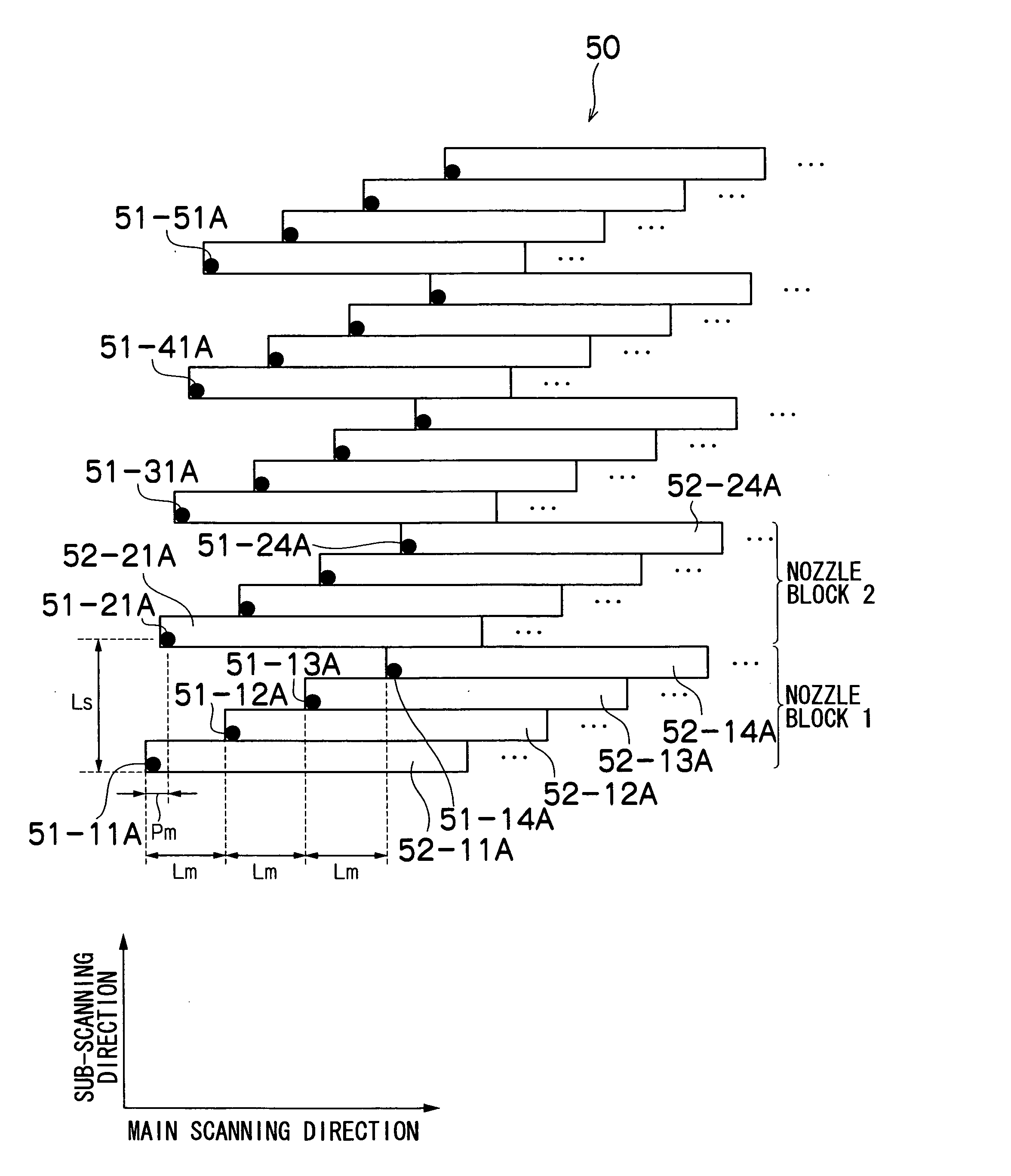
[0054] In the liquid droplet discharge head according to the present invention, when arranging the nozzles in a two-dimensional matrix array, the nozzles are displaced with respect to each other as described in detail below, rather than simply arranging the nozzles in an oblique fashion as in the related art. Therefore, the time interval between the ejection of droplets which are discharged from different nozzles and overlap mutually on the recording medium is increased, thereby preventing landing interference between adjacent dots.

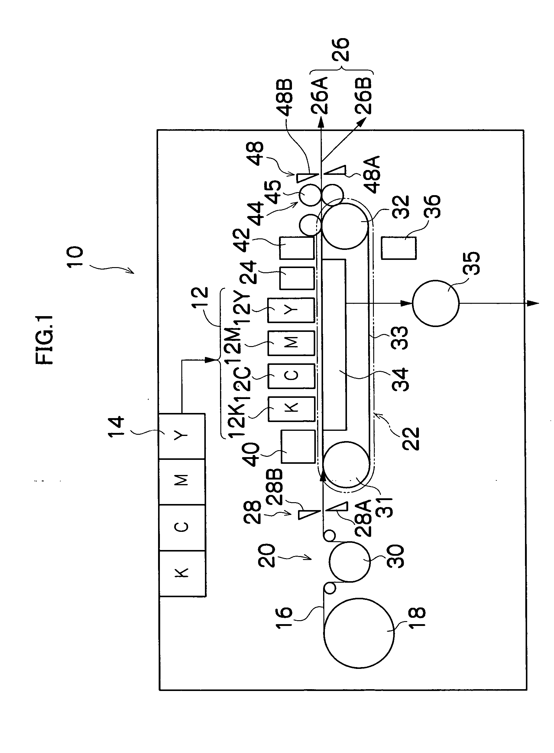
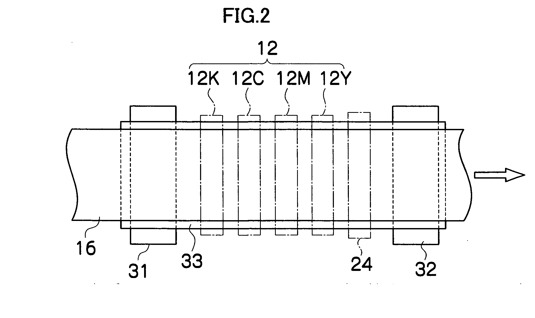
[0055]FIG. 1 is a general schematic drawing of an inkjet recording apparatus according to an embodiment of the present invention. As shown in FIG. 1, the inkjet recording apparatus 10 comprises: a printing unit 12 having a plurality of droplet discharge heads or print heads 1...


PUM


Abstract

The liquid droplet discharge head comprises: a plurality of nozzles which discharge liquid droplets onto a recording medium, wherein the nozzles are arranged two-dimensionally in a main scanning direction perpendicular to a conveyance direction in which the recording medium is conveyed relatively with respect to the liquid droplet discharge head, and a sub-scanning direction which coincides with the conveyance direction, in such a manner that: at least a portion of dots formed by the droplets deposited on the recording medium from the nozzles overlap mutually in the main scanning direction; and with respect to a first nozzle and a second nozzle which discharge droplets to form mutually adjacent dots in the main scanning direction on the recording medium, and with respect to a third nozzle which is adjacent to the first nozzle in the sub-scanning direction, positions of the first nozzle and the second nozzle are separated in the sub-scanning direction by at least a distance equal to a multiple by an integer that is at least two, of a distance between the first nozzle and the third nozzle in the sub-scanning direction, and positions of the first nozzle and the third nozzle are separated in the main scanning direction by at least a distance equal to a maximum dot diameter formed by the liquid droplets discharged onto the recording medium from the first nozzle and the third nozzle.

Description

BACKGROUND OF THE INVENTION [0001] 1. Field of the Invention [0002] The present invention relates to a liquid droplet discharge head and an image forming apparatus, and more specifically, to a liquid droplet discharge head and an image forming apparatus in which nozzles which discharge liquid droplets are arranged in a two-dimensional matrix array. [0003] 2. Description of the Related Art [0004] Inkjet recording apparatuses (inkjet printers) having an inkjet head (ink ejection head) in which a plurality of nozzles are arranged, are known as image forming apparatuses. An inkjet recording apparatus of this kind forms images by forming dots on a recording medium, by ejecting ink as droplets from nozzles, while causing the inkjet head and the recording medium to move relatively to each other. [0005] Various methods are known conventionally as ink discharge methods for an inkjet recording apparatus of this kind. For example, one known method is a piezoelectric method, where the volume of...

Claims


Application Information

Patent Timeline
Patent Type & Authority Applications(United States)
IPC IPC(8): B41J2/055B41J2/045B41J2/145
CPCB41J2/145
Inventor YAMANOBE, JUN
Owner FUJIFILM CORP
Why Eureka
Try Eureka