
Method and system for recording images

Inactive Publication Date: 2005-08-25
FUJIFILM HLDG CORP +1
View PDF13 Cites 4 Cited by
  • Summary
  • Abstract
  • Description
  • Claims
  • Application Information

AI Technical Summary

Benefits of technology

[0028] In addition, the single scanning operation can prevent the problem of positional shift caused when scanning is performed a plur

Problems solved by technology

At this stage, the resist layer formed on the through hole is inferior to other parts in mechanical strength, so resist patterns are sometimes damaged in the aforementioned development and etching processes.
However, since it takes time for laser light to become stable, it is fairly difficult to perform exposure while suitably changing the intensity of laser light.
The amount of the time needed to record resist patterns is two times or more of that of the conventional method, so it is d

Method used


Image

  • Method and system for recording images
  • Method and system for recording images
  • Method and system for recording images

Examples


Embodiment Construction

[0073] As a preferred embodiment of an image recording method of the present invention, a description will hereinafter be given of a pattern recording method used when recording wiring patterns on a substrate in a printed circuit board fabrication step.

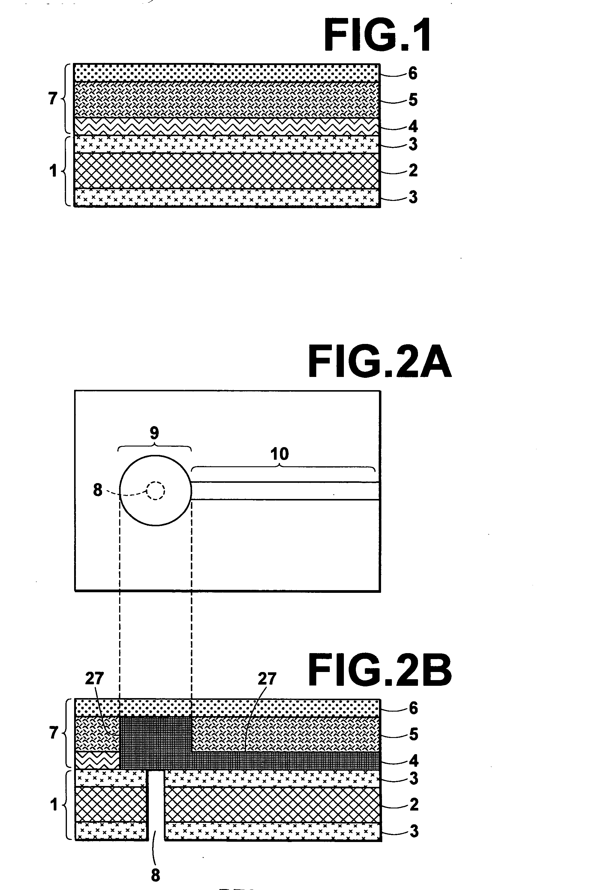
[0074]FIG. 1 shows a substrate 1 on which wiring patterns are to be formed. A resist film 7 has been stuck on the substrate 1. The substrate 1 on which the resist film 7 has been stuck is called a recording medium where necessary.

[0075] As shown in FIG. 1, the substrate 1 comprises a glass epoxy substrate material 2, and thin films of copper 3 stacked on both surfaces of the substrate material 2. The resist film 7 comprises a support layer 6, a thick-film low-photosensitive layer 5 (hereinafter referred to as a thick photosensitive layer 5) stacked on the support layer 6, and a thin-film highly-photosensitive layer 4 (hereinafter referred to as a thin photo sensitive layer 4) stacked on the thick photo sensitive layer 5. As shown in...


PUM


Abstract

Binary image data representing a desired image is first generated, and on-off control of an energy beam scanning a recording medium is performed based on a value of each pixel data constituting the binary image data to record the image on the recording medium. Some pixel data are then selected from pixel data of the binary image data that have a first value turning on the energy beam, and the first value of the some pixel data is replaced with a second value turning off the energy beam. The on-off control is performed based on the first or second value of each pixel data constituting binary image data obtained after the first value is replaced with the second value.

Description

BACKGROUND OF THE INVENTION [0001] 1. Field of the Invention [0002] The present invention relates to a method and system for recording patterns, such as characters, figures, etc., on a recording medium by scanning laser light, etc. [0003] 2. Description of the Related Art [0004] There is known in the image recording art a system which irradiates laser light modulated with a spatial light modulator to a photosensitive recording medium to record images (e.g., see Japanese Unexamined Patent Publication No. 2003-345030). Also known in the prior art is a system which selectively applies a voltage to linearly arranged exothermic resistance elements to record images on a photosensitive recording medium. In these systems, binary image data representing an image is first generated or acquired. Then, an energy beam, such as light, heat, etc., which scans a recording medium is turned on-and-off based on a value of each pixel data constituting the binary image data. [0005] For example, the syst...

Claims


Application Information

Patent Timeline
IPC IPC(8): B41J2/355G03F7/20H04N1/40H05K3/00
CPCB41J2/355H05K3/0082H04N1/40031
Inventor SASAKI, YOSHIHARU
Owner FUJIFILM HLDG CORP
Learn More