Recording system, recording apparatus, information processing apparatus, and recording control method

a recording system and recording technology, applied in the field of recording systems, can solve the problems of preventing the ink from being properly ejected, the recording apparatus using the inkjet recording head, and not carrying out proper recording, so as to achieve high-quality image recording and efficiently reduce the load on specific nozzles

Active Publication Date: 2014-06-05
COPYER
View PDF24 Cites 0 Cited by
  • Summary
  • Abstract
  • Description
  • Claims
  • Application Information

AI Technical Summary

Benefits of technology

[0010]The present invention has been made in view of the above-mentioned related art example, and provides a recording system, a recording apparatus, an information processing apparatus, and a recording control method which ensures high-quality image recording based on the head shading while efficiently reducing a load on specific nozzles of a recording head.

Problems solved by technology

In general, a recording apparatus using an inkjet recording head (hereinafter referred to as “recording head”) may not carry out proper recording when the number of ejections of ink from nozzles of the recording head exceeds a predetermined value.
This may prevent the ink from being properly ejected, lowering the quality of a recorded image.
There is thus a problem in that, when the amount of image shift changes abruptly due to, for example, interruption of a job, image shift which cannot be identified in the head shading processing is performed so that the correction is not reflected properly.

Method used


Image

  • Recording system, recording apparatus, information processing apparatus, and recording control method
  • Recording system, recording apparatus, information processing apparatus, and recording control method
  • Recording system, recording apparatus, information processing apparatus, and recording control method

Examples


first embodiment

[0041]Now, referring to FIGS. 1 to 11, a description will be provided of a first embodiment of the present invention more specifically and in detail.

[0042]The term “record” (hereinafter sometimes referred to as “print”) used herein means formation of not only significant information such as characters and figures, but also insignificant information. Further, the term represents formation of an image, a design, a pattern, or the like on a recording medium, or processing of a medium in a broad sense, regardless of whether such is apparent as being visibly sensible by persons.

[0043]The term “recording medium” represents not only a sheet of paper which is used for an ordinary recording apparatus, but also any medium on which ink is applicable, such as cloth, plastic film, metal plate, glass, ceramics, wood, or leather, in a broad sense.

[0044]Further, the term “ink” (hereinafter sometimes referred to as “liquid”) should be broadly interpreted like the above-mentioned definition of “recor...

example 1

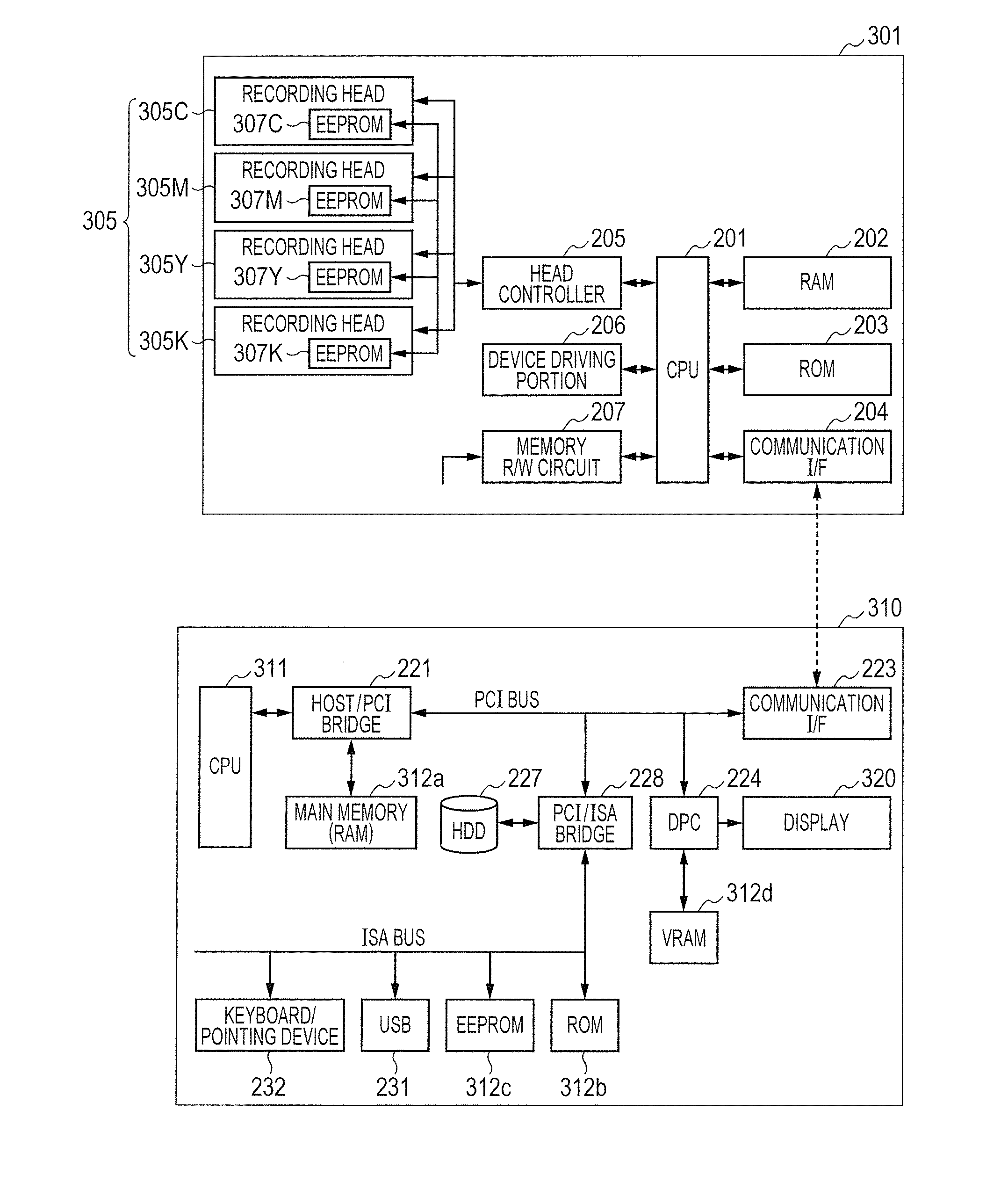
[0081]FIG. 7 is a diagram illustrating data stored in respective RAMs of the information processing apparatus 310 and the recording apparatus 301 to execute the recording operation according to Example 1 of the present invention.

[0082]As illustrated in FIG. 7, the RAM 312a of the information processing apparatus 310 stores image data 121 to be used in recording, information of uneven density of nozzle 122 of the recording apparatus 301, a judgement flag of HS processing 123 for judging whether to execute HS processing, an amount of image shift 124 acquired by the recording apparatus 301, and the like. The RAM 202 of the recording apparatus 301 stores information of uneven density of nozzle 131, a count value of printed pages 132, a threshold value of image shift 133 at the time of executing image shift, a table of values of image shift 134, which defines a plurality of amounts of image shift, and the like. The RAM 202 of course stores image data to be used in recording in addition t...

example 2

[0099]FIG. 10 is a diagram illustrating data stored in RAMs of the information processing apparatus 310 and the recording apparatus 301 to execute the recording operation according to Example 2 of the present invention. In FIG. 10, the same reference numerals are given to the same data as described above referring to FIG. 7 to avoid repeating the redundant description. The following describes only data unique to Example 2.

[0100]As apparent from FIG. 10 in comparison with FIG. 7, data to be stored in the RAM 312a of the information processing apparatus 310 is the same as the data in Example 1. The RAM 202 of the recording apparatus 301 stores a value 132a representing the number of printed pages.

[0101]Because the processing which is executed by the information processing apparatus 310 in Example 2 is the same as the one described in Example 1 referring to FIG. 8, the description thereof is omitted, and only processing associated with the recording operation of the recording apparatus...


PUM


Abstract

A recording system, including: a recording apparatus configured to perform recording using a recording head having a plurality of recording elements; and an information processing apparatus configured to send a print job to the recording apparatus to shift a range of use of the recording elements in an array direction of the recording elements, the information processing apparatus including: a head shading correction unit configured to execute, based on information indicating that the range of use of the recording elements is one of ranges of use, head shading correction corresponding to the one range on image data; and a sending unit configured to send the image data subjected to the head shading correction to the recording apparatus, the recording apparatus including a recording control unit configured to control the recording head to perform recording at the one range by using the image data subjected to the head shading correction.

Description

BACKGROUND OF THE INVENTION[0001]1. Field of the Invention[0002]The present invention relates to a recording system, a recording apparatus, an information processing apparatus, and a recording control method, and more particularly, to a recording system which includes a recording apparatus having recording heads mounted therein and an information processing apparatus connected to the recording apparatus, and a recording control method used in the recording system.[0003]2. Description of the Related Art[0004]In general, a recording apparatus using an inkjet recording head (hereinafter referred to as “recording head”) may not carry out proper recording when the number of ejections of ink from nozzles of the recording head exceeds a predetermined value.[0005]When a recording head has an electrothermal converter (heater) as an ink ejection energy generating unit, for example, heat generated from the electrothermal converter rapidly heats the ink to produce bubbles whose pressure causes ...

Claims


Application Information

Patent Timeline
Patent Type & Authority Applications(United States)
IPC IPC(8): G06F3/12
CPCG06F3/1282G06F3/1208G06F3/121G06F3/1247
Inventor UEDA, KENJIONO, YASUKAZU
Owner COPYER
Why Eureka
Try Eureka