An intelligent electrical cabinet for temporary work

A technology for electrical cabinets and operations, which is applied to electrical components, substation/switch layout details, substation/distribution device shells, etc., can solve the problems of high cost, high labor intensity, and long time-consuming mobile electrical cabinets, and achieve time-consuming Short, low labor intensity, high work efficiency

Active Publication Date: 2019-07-12
高原(山东)机电设备有限公司
View PDF10 Cites 0 Cited by
  • Summary
  • Abstract
  • Description
  • Claims
  • Application Information

AI Technical Summary

Problems solved by technology

[0003] In order to solve the above-mentioned problems, the present invention provides an intelligent electrical cabinet for temporary operation, which can solve the problem that the installation position of the electrical cabinet needs to be manually leveled in the process of using the temporary electrical cabinet on the existing construction site. Lifting equipment to move electrical cabinets, temporary electrical cabinets need to be assembled on site, which takes a long time, manual leveling of the installation position, labor-intensive, manual use of lifting equipment to move electrical cabinets is costly, labor-intensive and low work efficiency and other problems , can realize the function of intelligent operation of temporary electrical cabinets on construction sites, without manual assembly of electrical cabinets, without manual leveling of the working surface, and has the advantages of good stability, short time-consuming, low labor intensity and high work efficiency.

Method used


Image

  • An intelligent electrical cabinet for temporary work
  • An intelligent electrical cabinet for temporary work
  • An intelligent electrical cabinet for temporary work

Examples


Embodiment Construction

[0018] In order to make the technical means, creative features, goals and effects achieved by the present invention easy to understand, the present invention will be further described below in conjunction with specific illustrations.

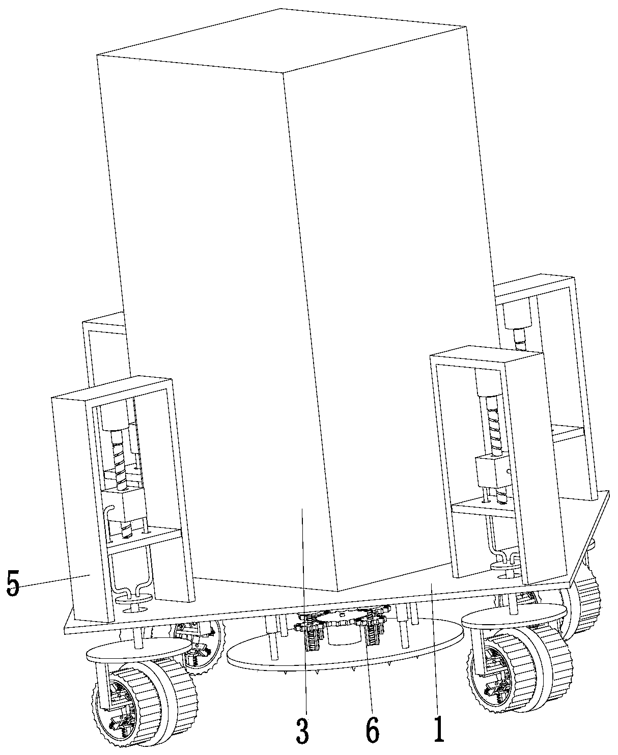
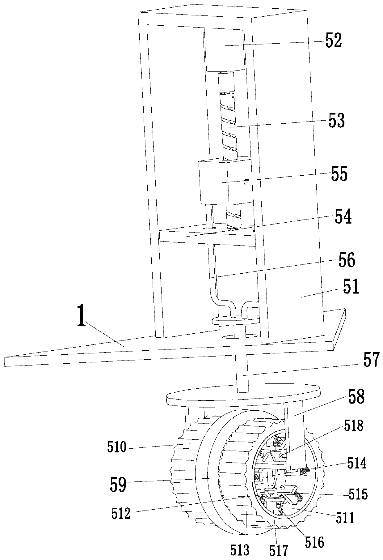
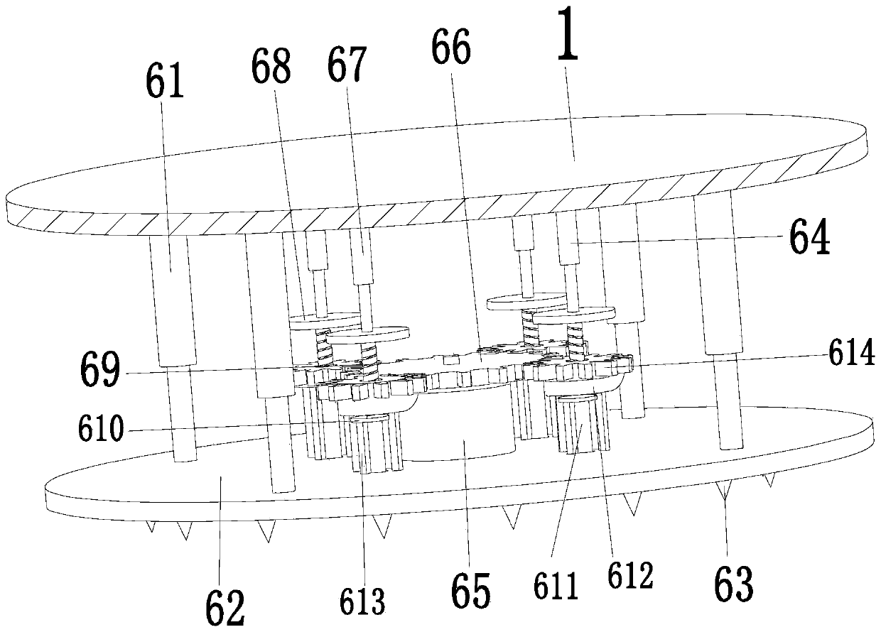
[0019] Such as Figure 1 to Figure 3 As shown, an intelligent electrical cabinet for temporary operation includes a bottom plate 1, an electrical cabinet body 3 is installed on the bottom plate 1, four sliding holes are arranged on the bottom plate 1, and a mobile fixing device 5 is arranged in each sliding hole , the middle part of the lower end of the bottom plate 1 is provided with a positioning device 6, the mobile fixing device 5 can assist the present invention to move and fix during work, and the positioning device 6 can ensure that the present invention can work stably at a designated position without manual operation, reducing the The labor intensity of the staff is improved, and the work efficiency is improved.

[0020]Described mobil...


PUM


Abstract

The invention relates to an intelligent electrical cabinet for temporary work. The intelligent electrical cabinet comprises a bottom plate which is equipped with an electric cabinet body and is provided with four sliding holes. Moving and fixing devices are arranged in the sliding holes, and a positioning device is arranged in the middle of the lower end of the bottom plate. The positioning devicecomprises a positioning telescopic cylinder installed on the bottom plate, a top end of the positioning telescopic cylinder is installed on a positioning support plate through a flange, and a lower end of the positioning support plate is uniformly provided with positioning cone blocks. In the process of using a temporary electrical cabinet in an existing construction site, the installation position of the electrical cabinet needs to be manually levelled, the manual movement of the electrical cabinet needs existing lifting equipment, the temporary electrical cabinet needs to be assembled in the site, a long time is taken, the labor intensity is high when the installation position of the electrical cabinet is manually levelled, the cost is high when the electrical cabinet is manually movedwith the existing lifting equipment, and the above problems are solved according to the intelligent electrical cabinet.

Description

technical field [0001] The invention relates to the field of electric equipment, in particular to an intelligent electrical cabinet for temporary operations. Background technique [0002] The electrical cabinet is a cabinet made of steel to protect the normal operation of components. The materials for making electrical cabinets are generally divided into two types: hot-rolled steel plates and cold-rolled steel plates. Compared with hot-rolled steel sheets, cold-rolled steel sheets are softer and more suitable for the production of electrical cabinets. In the early stage of construction on the construction site, in order to ensure that the normal operation of the construction equipment can be effectively controlled, a temporary electrical cabinet needs to be installed. When the expected effect is achieved, the temporary electrical cabinet needs to be removed. Manual leveling of the installation position of the electrical cabinet requires manual use of existing lifting equip...

Claims


Application Information

Patent Timeline
IPC IPC(8): H02B1/52H02B1/30
CPCH02B1/30H02B1/52
Inventor 徐盼盼
Owner 高原(山东)机电设备有限公司
Why Eureka
Try Eureka