Crosslinked cable hot melting connector and manufacturing method thereof

A production method and welding joint technology, applied in the field of power cables, can solve problems such as failure to quickly restore power supply, potential safety hazards of the power supply system, and loss expansion, and achieve the effects of avoiding interfacial air gap discharge, easy on-site production, and maintaining conductivity

Pending Publication Date: 2018-10-19
CHANGYUAN ELECTRIC TECH
View PDF9 Cites 5 Cited by
  • Summary
  • Abstract
  • Description
  • Claims
  • Application Information

AI Technical Summary

Problems solved by technology

Since the operating environment of power cables is mostly directly buried, the cables or joints are damaged due to various reasons such as later construction, cable failure, and external force damage. If the damage is serious, it is necessary to remove the severely burned part of the cable before installing the joint, and dig out the cable to straighten it to supplement, but it requires a lot of manpower, material resources and time, and cannot meet the requirements of fast restoration of power; or add a section of cable in the middle to make two Connect with a cable joint, which increases the material cost, and the repair time is long, which expands the loss.
[0003] At present, there are several types of cable joints, such as cold-shrinkable, heat-shrinkable, prefabricated, and glue-filled. The length of these types of cable joints is relatively fixed. Before installation, the cables at both ends must be aligned. Different from the cable material, there is an interface air gap between different materials, which is prone to interfacial air gap discharge, causing cable joint failure, and bringing safety hazards to the power supply system

Method used


Image

  • Crosslinked cable hot melting connector and manufacturing method thereof
  • Crosslinked cable hot melting connector and manufacturing method thereof
  • Crosslinked cable hot melting connector and manufacturing method thereof

Examples


Embodiment Construction

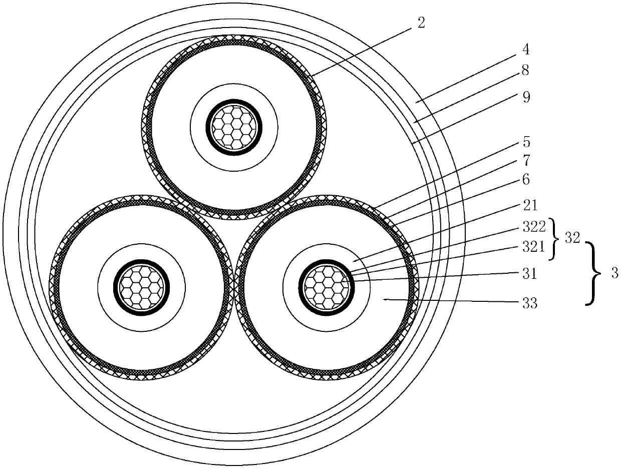
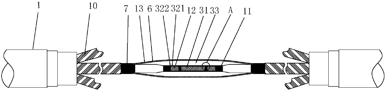
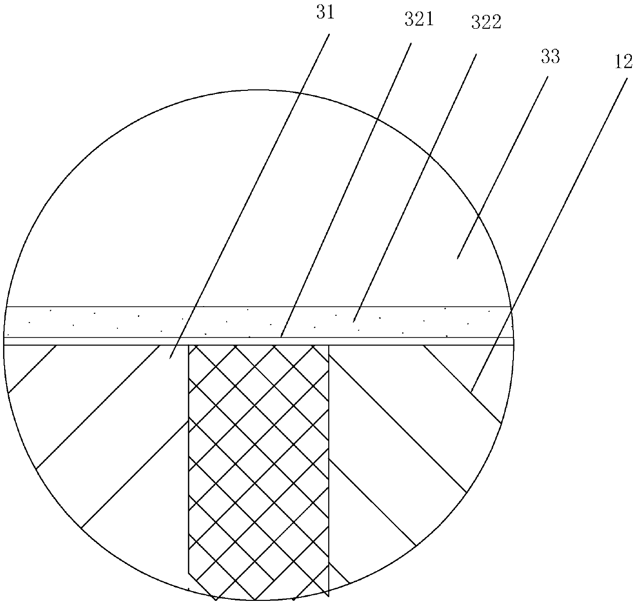
[0039] see Figure 1 to Figure 3 , a cross-linked cable hot-melt joint of the present invention is used to connect the protective layer 1 of the cable and the cable 2 placed in the protective layer 1, wherein the protective layer 1 includes an armor layer, an outer sheath and an inner sheath , the armor layer is arranged between the outer sheath and the inner sheath; the cable 2 includes a copper shielding layer 10, a conductor shielding layer 11, a cable outer semiconductive layer 7, a cable conductor 12 and a cable insulation layer 21, and the conductor shielding layer The layer 11 is wrapped around the cable conductor 12 , and the conductor shielding layer 11 is set outside the cable outer semiconductive layer 7 , and the cable outer semiconductive layer 7 is set outside the cable insulating layer 21 .

[0040] This joint structure includes a connection group 3 for connecting the cable 2 and a sheath group 4 for connecting the protective layer 1, the sheath group 4 is wrapp...


PUM


Abstract

The invention discloses a crosslinked cable hot melting connector which is used for the protection layer connecting the cable and the cable arranged in the protection layer. The crosslinked cable hotmelting connector comprises a connecting group and a sheath group. The sheath group wraps outside the connecting group. The connecting group comprises a melting body which is used for connecting the internal conductor of the cable in a melting way, an internal semi-conductive layer which wraps outside the melting body and the conductor and an insulator. The internal semi-conductive layer is connected with a conductor shielding layer. The insulator wraps outside the internal semi-conductive layer. The insulator is externally connected with a cable insulating layer. According to the crosslinkedcable hot melting connector, the connecting group is used for connecting the cable and the sheath group is used for connecting the protection layer so as to realize double-layer protection; the connecting group can keep great conductivity so as to avoid cable breakdown caused by electric field stress concentration; and the shielding paint layer is arranged on the insulator so that the situation ofcable arc breakdown can be avoided, the external semi-conductive layer is connected with the galvanized copper mesh layer so that the whole cable insulating shielding is enabled to be completely andreliably recovered. The cable connector can be manufactured onsite so that operation is convenient, the cost is low and the cable connector is suitable for popularization.

Description

technical field [0001] The invention relates to the technical field of power cables, in particular to a cross-linked cable hot-melt joint and a manufacturing method thereof. Background technique [0002] With the progress of urban power grid reconstruction projects, it has become a trend for power cables to replace overhead lines. Power cables have the advantages of good insulation performance, large transmission capacity, light structure, and are not limited by height differences, occupying an absolute advantage in the field of cable applications. status. Since the operating environment of power cables is mostly directly buried, the cables or joints are damaged due to various reasons such as later construction, cable failure, and external force damage. If the damage is serious, it is necessary to remove the severely burned part of the cable before installing the joint, and dig out the cable to straighten it to supplement, but it requires a lot of manpower, material resourc...

Claims


Application Information

Patent Timeline
Patent Type & Authority Applications(China)
IPC IPC(8): H02G15/18H02G15/188H02G1/14
CPCH02G1/145H02G15/1806H02G15/188
Inventor 胡飞强卫刘夏黄成龙张俊杰夏云杰谢德良
Owner CHANGYUAN ELECTRIC TECH
Why Eureka
Try Eureka