
Spine prosthesis based on 3D printing and making method thereof

A 3D printing, prosthesis technology, applied in 3D printing, prosthesis, spinal implants, etc., can solve the problem of high pressure load on the surface of the vertebral body endplate, structural damage of the vertebral body endplate, titanium cage piercing into the vertebral body, etc. To achieve the effect of promoting stability and bony fusion, ensuring long-term stability, and strengthening holding power

Pending Publication Date: 2018-10-23
陕西东望科技有限公司
View PDF10 Cites 7 Cited by
  • Summary
  • Abstract
  • Description
  • Claims
  • Application Information

AI Technical Summary

Problems solved by technology

This point contact method causes a large pressure load on the surface of the vertebral body endplate, which is likely to cause structural damage to the vertebral body endplate and cause the titanium cage to penetrate into the vertebral body, causing the titanium cage to collapse (Xu Jianwei, Jia Lianshun, Chen Deyu, et al. Discussion on early collapse of titanium mesh bone graft in subtotal vertebral body resection[J]. Chinese Journal of Orthopedic Surgery, 2002,10(z1):1267-1269.)

Method used


Image

  • Spine prosthesis based on 3D printing and making method thereof
  • Spine prosthesis based on 3D printing and making method thereof
  • Spine prosthesis based on 3D printing and making method thereof

Examples


Embodiment Construction

[0053] The present invention will be further described in detail below in conjunction with specific embodiments, which are explanations of the present invention rather than limitations.

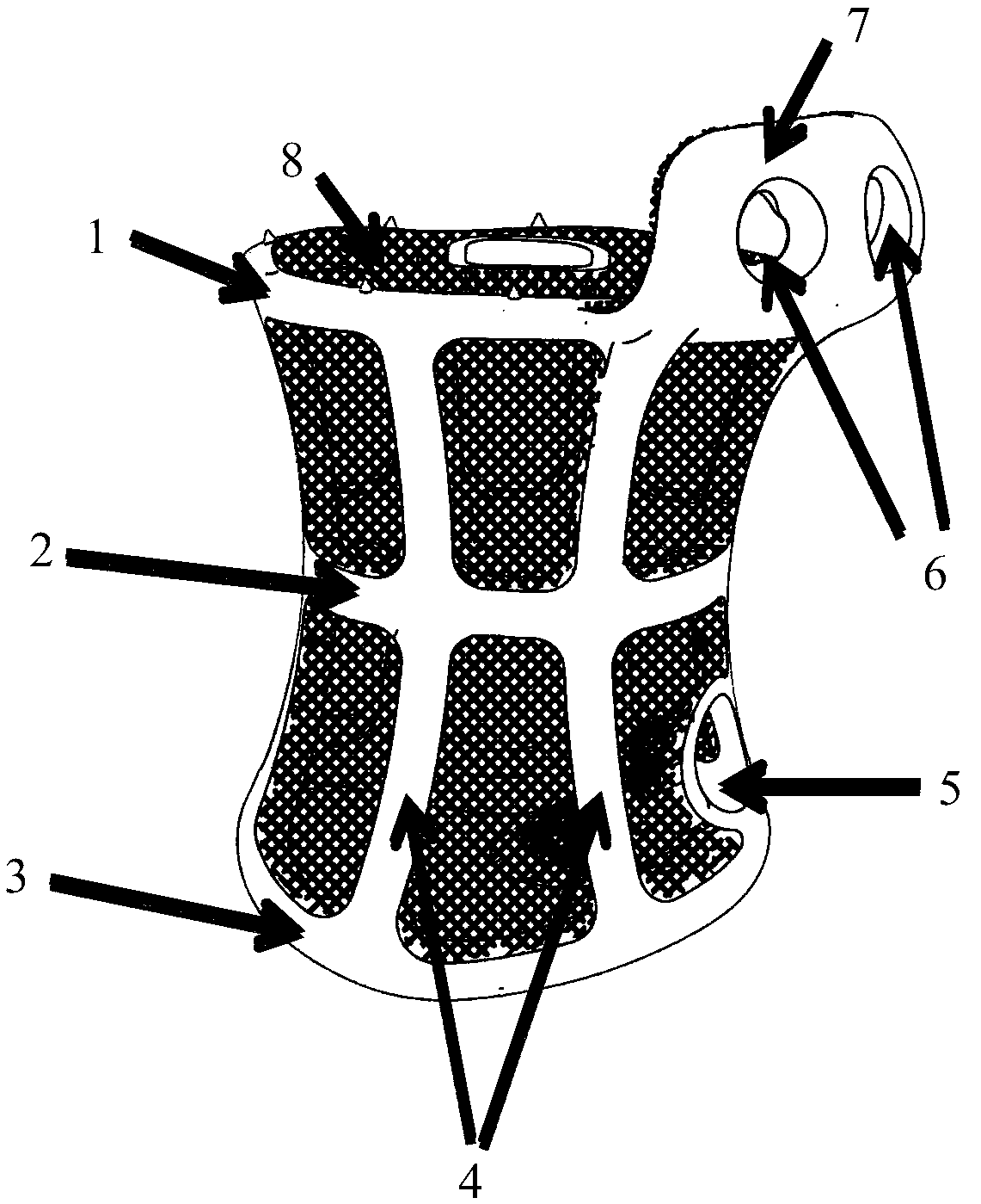
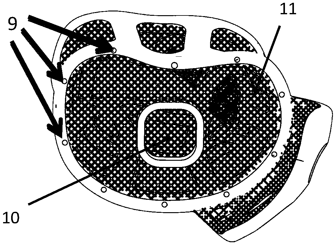
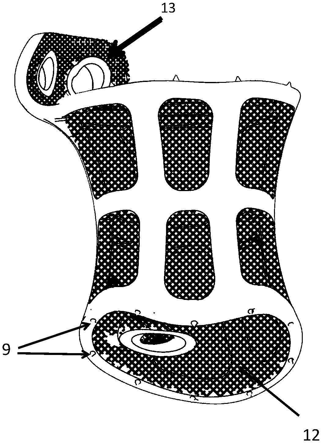
[0054] refer to Figure 1-Figure 6 , a spinal prosthesis based on 3D printing, including a support frame, a hollow structure and a fixation position;

[0055] The support frame is a cavity-type main force-bearing structure composed of beams and longitudinal beams. The beams include an upper bolster, a lower bolster and an intermediate beam. The upper bolster and the lower bolster are respectively in contact with the The anatomical shape of the surface of the vertebral body matches, there are several longitudinal beams distributed between the upper bolster and the lower bolster, and the middle beam is connected between the longitudinal beams;

[0056] The hollow structure is a non-main stress-bearing part distributed between the supporting frames, and is used to induce the penetration and gro...


PUM

PropertyMeasurementUnit
Apertureaaaaaaaaaa
Thicknessaaaaaaaaaa
Apertureaaaaaaaaaa

Abstract

The invention discloses a spine prosthesis based on 3D printing and a making method thereof. The spine prosthesis comprises supporting frames, hollowed-out structures and fixing parts; each supportingframe is of a cavity-type main body stress structure formed by multiple transverse beams and longitudinal beams, each transverse beam comprises an upper bearing beam, a lower bearing beam and a middle transverse beam body, the upper bearing beams and the lower bearing beams are matched with the centrum surfaces in contact with the upper bearing beams and the lower bearing beams in dissection shape respectively, multiple longitudinal beams are distributed between the upper bearing beams and the lower bearing beams, and the middle transverse beam bodies are connected among the longitudinal beams; the hollowed-out structures are non-main-stress parts distributed among the supporting frames. According to the spine prosthesis, the upper and lower bearing beams are required to be designed in reference to the dissection shapes of the adjacent upper and lower centrum surfaces and completely attached to each other during installation, conical fixing spine structures are evenly distributed, theholding force is reinforced, and accordingly fixing is more stable; the main body structure is a waisted structure and is beneficial to effective conduction of a load and stress diffusion. The cavitydesign and opening design are adopted for the interior of the supporting frame, the supporting frame is used for containing the bone tissue, and synostosis of the upper and lower centrums is promoted.

Description

technical field [0001] The invention belongs to the technical field of medical implant prosthesis, and relates to a spinal prosthesis based on 3D printing and a preparation method thereof. Background technique [0002] Spinal tumors refer to primary and secondary tumors that occur in the spine. The overall incidence of primary spinal tumors is approximately 0.4%. The vast majority of adolescent spinal tumors are benign, while young and middle-aged patients are more likely to have malignant tumors. Benign tumors mostly involve the posterior structures, while malignant tumors mostly involve the vertebral bodies. Primary benign spinal tumors generally progress slowly and have a long course of disease; malignant spinal tumors progress faster, have a shorter course of disease, and appear faster in clinical symptoms, accounting for about 10% of new malignant bone tumors every year. For malignant spinal tumors that affect the stability of the spine, surgical tumor resection and ...

Claims


Application Information

Patent Timeline
IPC IPC(8): A61F2/30A61F2/44B33Y10/00B33Y80/00
CPCA61F2/30942A61F2/44B33Y10/00B33Y80/00A61F2002/30985A61F2002/30772
Inventor 陈卫董涛黄鸿
Owner 陕西东望科技有限公司
Learn More