
A gear milling machine capable of changing height

A technology of changing height and gear milling machine, applied in the direction of gear cutting machine, gear teeth, mechanical equipment, etc., can solve problems such as affecting the processing efficiency of workpieces, and achieve the effect of improving clamping and installation efficiency, improving processing efficiency, and reducing replacement frequency.

Active Publication Date: 2020-04-24
CHONGQING HANYUAN MACHINERY
View PDF8 Cites 0 Cited by
  • Summary
  • Abstract
  • Description
  • Claims
  • Application Information

AI Technical Summary

Problems solved by technology

[0002] The gear milling machine is a kind of equipment for processing gears. Its main function is to mill the gear surface. Before milling the gear surface, it is necessary to install cutting tools on the gear milling machine. At the same time, because the gear is especially Different tools need to be replaced to make the taper of the bevel gear inconsistent. At this time, the replacement of the tool seriously affects the processing efficiency of the workpiece. Therefore, a gear milling machine that can change the height is needed.

Method used


Image

  • A gear milling machine capable of changing height
  • A gear milling machine capable of changing height

Examples


Embodiment Construction

[0017] The following will clearly and completely describe the technical solutions in the embodiments of the present invention with reference to the accompanying drawings in the embodiments of the present invention. Obviously, the described embodiments are only some, not all, embodiments of the present invention.

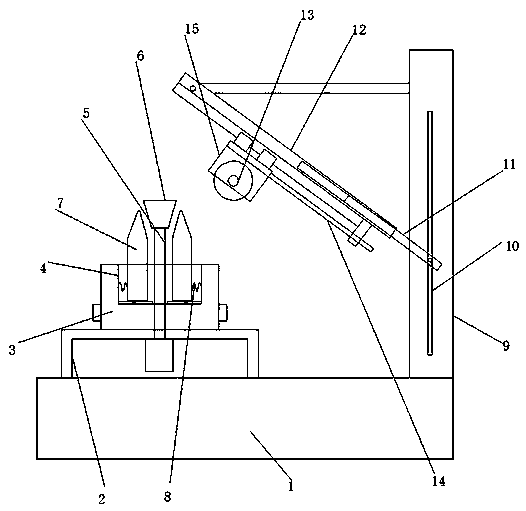
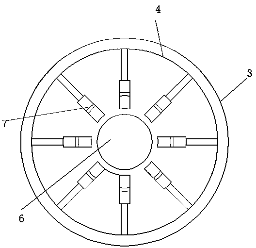
[0018] refer to Figure 1-2 , a gear milling machine capable of changing the height, comprising a mounting base 1, a bracket 2 is welded on the top of the mounting base 1, a mounting platform 3 is rotatably installed above the bracket 2, and the end of the mounting platform 3 away from the bracket 2 is provided with a mounting platform 3 coaxial cylindrical installation groove 4, the inner movable socket of the installation groove 4 is connected with the rotating shaft 5, and the rotating shaft 5 and the installation groove 4 are coaxially arranged, and one end of the rotating shaft 5 is welded with a frustum-shaped pressing block 6, and the pressing block 6 is locat...


PUM


Abstract

The invention discloses a gear milling machine capable of changing height. The gear milling machine comprises a mounting base, wherein a bracket is welded above the mounting base; a mounting table isrotatably mounted above the bracket; one end, away from the bracket, of the mounting table is provided with a cylindrical mounting slot which is coaxial with the mounting table; the inner part of themounting slot is movably connected with a rotary shaft in a sleeving mode; the rotary shaft is coaxial with the mounting slot; one end of the rotary shaft is welded with a circular table shaped pressing block; the pressing block is positioned above the mounting slot; the outer side of the rotary shaft is equipped with a movable pressing block which is in sliding connection with the inner wall of the bottom of the mounting slot in an arrayed mode in the axial direction; and one side, away from the rotary shaft, of the movable pressing block is equipped with a spring which is connected with theside wall of the rotary shaft. The gear milling machine improves clamping and mounting efficiency of workpieces, saves workpiece mounting time, and regulates different height and inclination of a tool, so that the tool is suitable for cutting processing of gears with different sizes and inclinations, and therefore, a tool adapting direction of the gear milling machine is improved, tool replacing frequency is reduced, and gear processing efficiency is improved.

Description

technical field [0001] The invention relates to the technical field of gear milling machines, in particular to a gear milling machine capable of changing height. Background technique [0002] The gear milling machine is a kind of equipment for processing gears. Its main function is to mill the gear surface. Before milling the gear surface, it is necessary to install cutting tools on the gear milling machine. At the same time, because the gear is especially To make the taper of the bevel gear inconsistent, different tools need to be replaced. At this time, the replacement of the tool seriously affects the processing efficiency of the workpiece. Therefore, a gear milling machine that can change the height is needed. Contents of the invention [0003] The object of the present invention is to propose a gear milling machine capable of changing the height in order to solve the shortcomings in the prior art. [0004] In order to achieve the above object, the present invention a...

Claims


Application Information

Patent Timeline
Patent Type & Authority Patents(China)
IPC IPC(8): B23F23/06B23F23/12
CPCB23F23/06B23F23/1237
Inventor 罗昭成
Owner CHONGQING HANYUAN MACHINERY
Learn More