Truss type welding machine

A welding machine and truss-type technology, applied in the direction of welding equipment, auxiliary welding equipment, welding/cutting auxiliary equipment, etc., can solve the problems of inconvenient adjustment, reduced practical value, and inability to meet the requirements of welding trajectory, and achieve adjustable welding height. The effect of increasing the welding range

Inactive Publication Date: 2018-10-23
惠州市豪美仕智能技术有限公司
View PDF9 Cites 2 Cited by
  • Summary
  • Abstract
  • Description
  • Claims
  • Application Information

AI Technical Summary

Problems solved by technology

[0005] The purpose of the present invention is to provide a truss-type welding machine to solve the problem that the current welding machine proposed in the above background technology has a relatively single welding track, which cannot meet the requirements of a relatively complicated welding track, and the welding height needs to be manually set, resulting in adjustment Inconvenient, resulting in the inability to reflect the advantages of automation control well, and then reducing the practical value and other problems and deficiencies

Method used


Image

  • Truss type welding machine
  • Truss type welding machine
  • Truss type welding machine

Examples


Embodiment approach

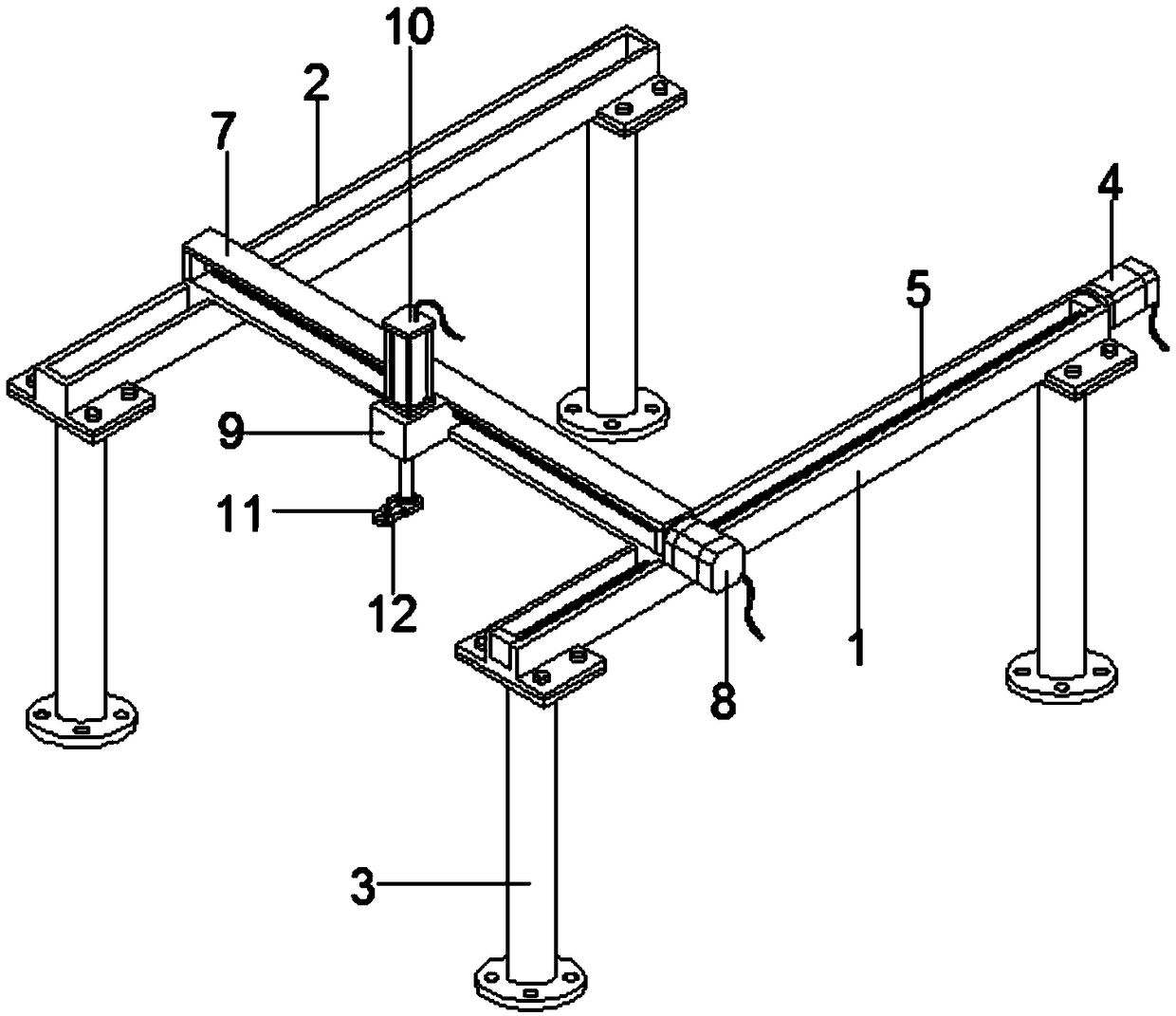
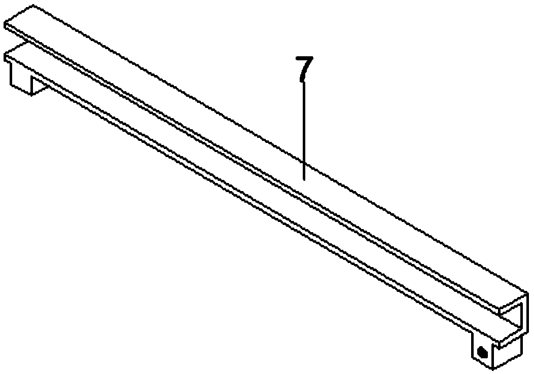
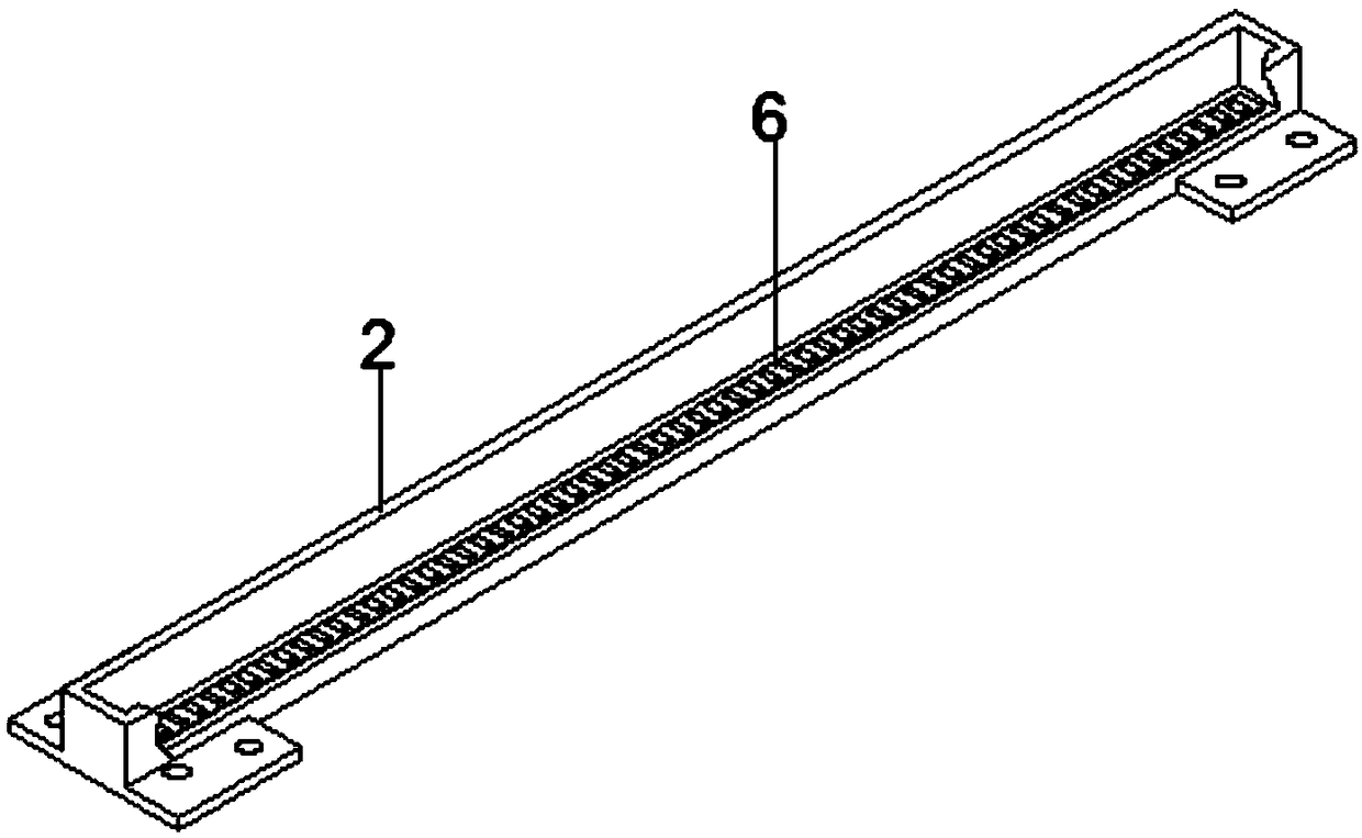
[0030] A truss-type welding machine, comprising: a first longitudinal beam 1, a second longitudinal beam 2, a column 3, a Y-axis motor 4, a lead screw 5, a roller guide rail 6, a horizontal frame 7, an X-axis motor 8, and a slider 9 , cylinder 10, clamp 11, clamping block 12; the second longitudinal beam 2 is arranged on one side of the first longitudinal beam 1, and the second longitudinal beam 2 is connected with the first longitudinal beam 1 through the cross frame 7; the columns 3 are respectively arranged At both ends of the bottom of the first longitudinal beam 1 and the second longitudinal beam 2, and the column 3 is connected with the first longitudinal beam 1 and the second longitudinal beam 2 by means of bolt fixing; the Y-axis motor 4 is installed on the first longitudinal beam 1 One end, and the Y-axis motor 4 is connected with the first longitudinal beam 1 by means of bolt fixing; the lead screw 5 is respectively arranged inside the first longitudinal beam 1 and th...


PUM


Abstract

The invention provides a truss type welding machine which comprises a first longitudinal beam, a second longitudinal beam and a transverse frame. The second longitudinal beam is arranged on one side of the first longitudinal beam, and the second longitudinal beam and the first longitudinal beam are connected through the transverse frame. Stand columns are arranged at the two ends of the bottom ofthe first longitudinal beam and the two ends of the bottom of the second longitudinal beam correspondingly, and the stand columns are connected with the first longitudinal beam and the second longitudinal beam in a bolt fixing manner. A Y-axis motor is arranged at one end of the first longitudinal beam and is connected with the first longitudinal beam in a bolt fixing manner. Lead screws are arranged in the first longitudinal beam and the transverse frame correspondingly and are connected with the first longitudinal beam and the transverse frame through a lead screw pair. Through the improvement on the machine, the advantages that the bidirectional operation manner is achieved, the welding range is widened, the welding height can be adjusted, and the function can be controlled based on automation are achieved; and therefore the problems and defects provided by the truss type welding machine in the background technology are effectively solved.

Description

technical field [0001] The present invention relates to the technical field of welding machines, and more specifically relates to a truss-type welding machine that can be controlled automatically. Background technique [0002] With the continuous development of welding technology, welding methods are increasingly pursuing automated operations, which can not only reduce manual operations but also greatly improve welding efficiency. To achieve automatic welding operations, a set of welding machines that can be based on automatic control must be used. Finish. [0003] However, the current welding machine has a relatively single welding track, which cannot meet the more complex welding track requirements, and the welding height needs to be set manually, resulting in inconvenient adjustment, resulting in the inability to fully reflect the advantages of automatic control, which in turn reduces the practical value. . [0004] In view of this, the existing problems are studied and...

Claims


Application Information

Patent Timeline
Patent Type & Authority Applications(China)
IPC IPC(8): B23K37/02
Inventor 黎志瀛
Owner 惠州市豪美仕智能技术有限公司
Why Eureka
Try Eureka