
Hydraulic pin puller for mine support

A pin puller and hydraulic technology, which is applied to hand-held tools, manufacturing tools, etc., can solve the problems of hydraulic support disassembly and maintenance labor intensity, increased support maintenance tasks, and troubled hydraulic support disintegration, etc. Easy to use, wide range of effects

Pending Publication Date: 2018-10-23
枣庄凯尔实业有限公司
View PDF0 Cites 4 Cited by
  • Summary
  • Abstract
  • Description
  • Claims
  • Application Information

AI Technical Summary

Problems solved by technology

[0002] The use of large mining height hydraulic supports is becoming more and more widespread. With the increase of mining height, the support height, working resistance and single frame weight of hydraulic supports are also getting higher and higher. Therefore, the base and connecting rods are connected with pins, shielding beams and connecting rods. The size of the connecting pin shaft, the connecting pin shaft between the cover beam and the top beam is also getting larger and larger. When the bracket needs to be overhauled in the well or overhauled underground, the removal of the large pin shaft is mostly done by manual brute force, the disassembly efficiency is low, and the safety hazard is great. It is the key link that troubles the smooth disintegration of the hydraulic support, and it is more laborious to disassemble after long-term use, which leads to the aggravation of the maintenance task of the support and brings great labor intensity to the disassembly and maintenance of the hydraulic support

Method used


Image

  • Hydraulic pin puller for mine support
  • Hydraulic pin puller for mine support
  • Hydraulic pin puller for mine support

Examples


Embodiment Construction

[0029] In order to make the object, technical solution and advantages of the present invention clearer, the present invention will be further described in detail below in conjunction with the accompanying drawings and embodiments. It should be understood that the specific embodiments described here are only used to explain the present invention, not to limit the present invention.

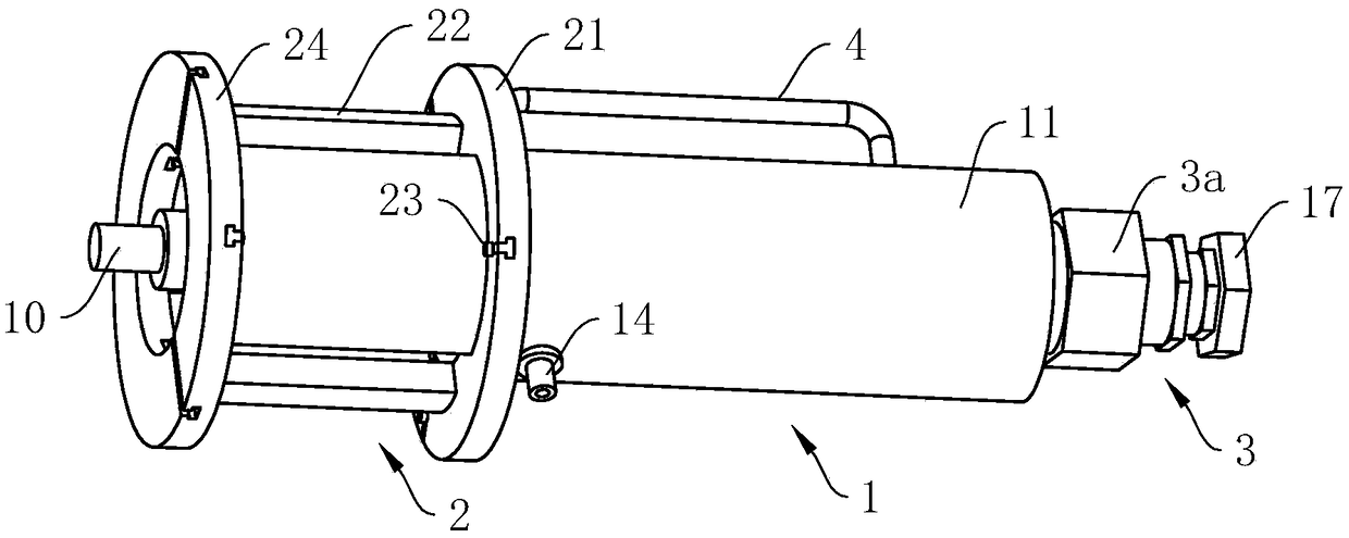
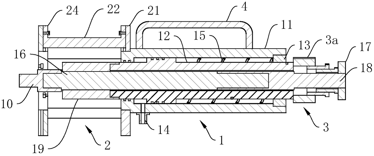
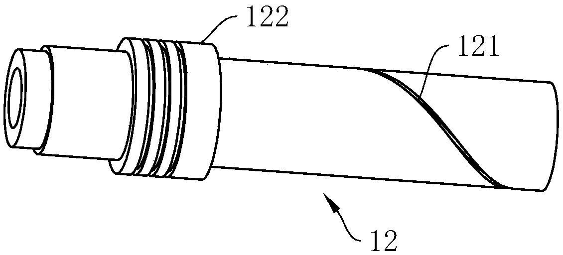
[0030] The mining support hydraulic pin puller provided by the present invention includes a detachably assembled extracting hydraulic cylinder and a supporting device; the extracting hydraulic cylinder includes a cylinder body, the sealing sleeve in the cylinder body is provided with a hollow piston rod, and the rear of the cylinder body The end is detachably fixed with a guide end cover, the outer peripheral surface of the rear section of the hollow piston rod is provided with a chute extending helically along its axial direction, and the inner wall of the guide end cover is provided with a matchin...


PUM


Abstract

The invention relates to the technical field of mining equipment, and provides a hydraulic pin puller for mine support. The hydraulic pin puller comprises a pull-out hydraulic cylinder and a supporting device which are detachably assembled together, wherein the pull-out hydraulic cylinder comprises a cylinder body; a hollow piston rod is arranged in the cylinder body in a sealing and sleeving mode; the rear end of the cylinder body is detachably fixed with a guide end cover; a pulling rod is arranged in the hollow piston rod in a sleeving mode; a pulling rod regulating device is arranged on the rear end part of the pulling rod; the rear end of the pulling rod is twisted with a limiting nut; the front end of the pulling rod is twisted with a pulling head; the power output end of the pullinghead is equipped with outer threads; the supporting device comprises a supporting pedestal which is detachably mounted at the front end of the cylinder body; and at least two arc-shaped supporting plates with inward openings are arranged on the supporting pedestal in a sliding mode. The hydraulic pin puller for the mine support provided by the invention is convenient to carry, is convenient to use, is high in pin pulling efficiency, is wide in scope of application, and is convenient to popularize and use.

Description

technical field [0001] The invention relates to the technical field of mining equipment, in particular to a hydraulic pin puller for a mining support. Background technique [0002] The use of large mining height hydraulic supports is becoming more and more widespread. With the increase of mining height, the support height, working resistance and single frame weight of hydraulic supports are also getting higher and higher. Therefore, the base and connecting rods are connected with pins, shielding beams and connecting rods. The size of the connecting pin shaft, the connecting pin shaft between the cover beam and the top beam is also getting larger and larger. When the bracket needs to be overhauled in the well or overhauled underground, the removal of the large pin shaft is mostly done by manual brute force, the disassembly efficiency is low, and the safety hazard is great. It is a key link that troubles the smooth disintegration of the hydraulic support, and it is more labori...

Claims


Application Information

Patent Timeline
IPC IPC(8): B25B27/02
CPCB25B27/026
Inventor 殷允忠李祥永蒋全海范伟褚大雷
Owner 枣庄凯尔实业有限公司
Learn More