Balance machine drive device
A driving device and balancing machine technology, applied in the field of balancing machines, can solve problems such as low production efficiency and labor force
- Summary
- Abstract
- Description
- Claims
- Application Information
AI Technical Summary
Problems solved by technology
Method used
Image

Examples
Embodiment 1
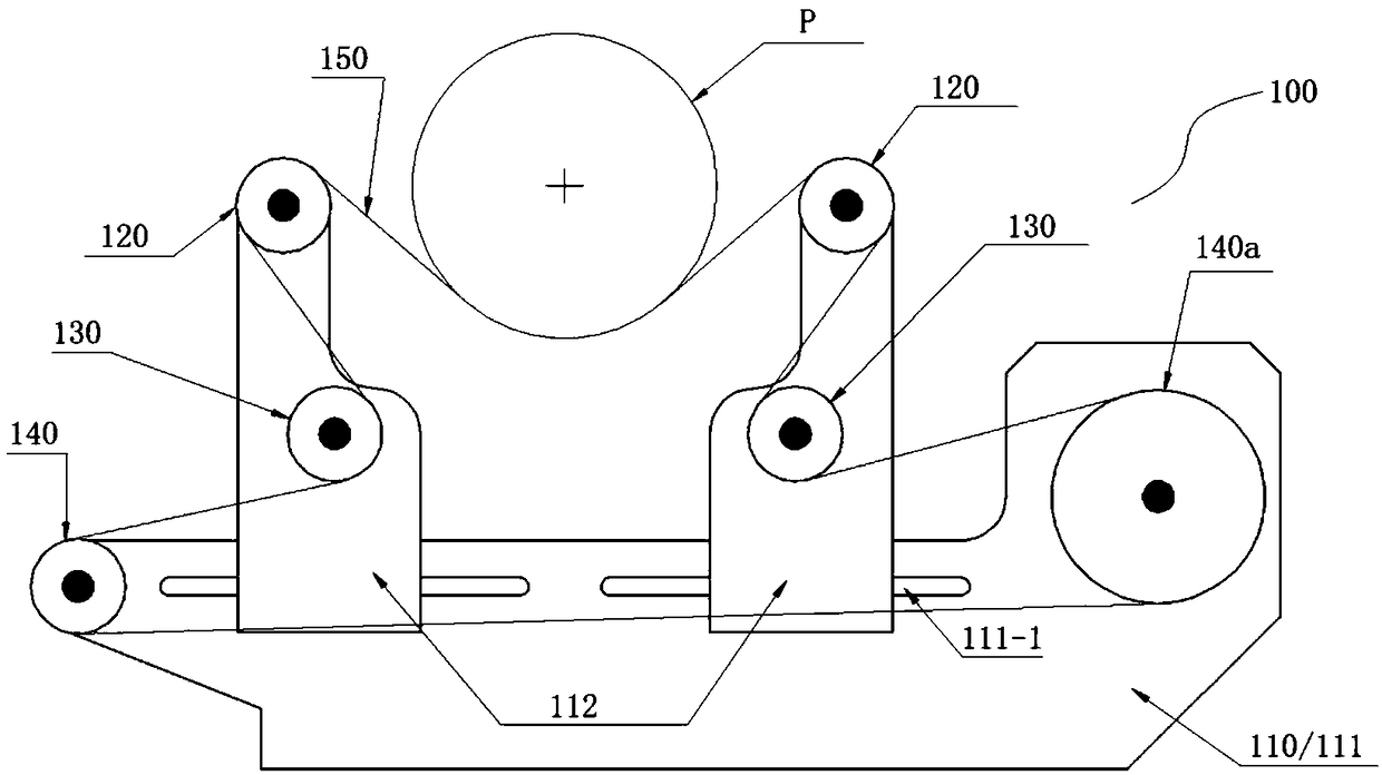
[0023] figure 1 It is a front view of a driving device of a balancing machine in the embodiment.
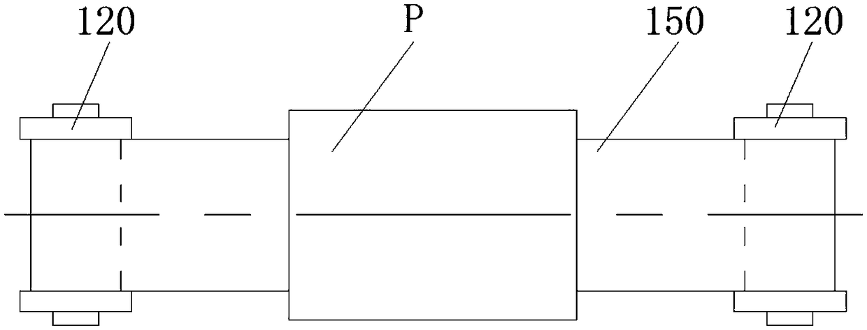
[0024] figure 2 It is a schematic top view of the workpiece and the positioning wheel of the balancing machine driving device in the first embodiment.
[0025] Such as figure 1 with figure 2 As shown, in this embodiment, the driving device of the balancing machine includes: a set of driving components 100 . The drive assembly includes: a drive frame 110, two positioning wheels 120, a drive wheel set, a drive belt 150 and a drive motor.
[0026] The driving frame 110 includes: a driving board 111 and two sliding boards 112 . There are two horizontal sliding slots 111 - 1 on the driving plate 111 , and the width and position height of the two horizontal sliding slots are consistent. Of course, it is also possible to form one horizontal chute through the two horizontal chutes 111 - 1 . The two slide plates 112 are arranged symmetrically, and the lower parts are respectively...
Embodiment 2
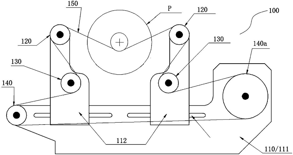
[0037] image 3 It is the front view of the driving device of the balancing machine in the second embodiment.
[0038] Figure 4 It is a schematic top view of the workpiece and the positioning wheel of the balancing machine driving device in the second embodiment.
[0039] Such as image 3 with Figure 4 As shown, in this embodiment, the driving device of the balancing machine includes: two sets of driving assemblies 100 , 200 . The two groups of driving assemblies are arranged symmetrically, and the structure of each group of driving assemblies is the same as that in Embodiment 1, and will not be described again.
[0040] In this embodiment, the workpiece P is a revolving body with small diameters at both ends (the same diameter at both ends) and a large middle diameter. One end of the workpiece P is placed on the transmission belt 150 between the two positioning wheels 120 of the driving assembly 100 , and the other end of the workpiece P is placed on the transmission b...
Embodiment 3
[0042] Figure 5 It is the front view of the driving device of the balancing machine in the third embodiment.
[0043] Image 6 It is a schematic plan view of the workpiece and the positioning wheel of the balancing machine driving device in the third embodiment.
[0044] Such as image 3 with Figure 4 As shown, in this embodiment, the driving device of the balancing machine includes: two sets of driving assemblies 100 , 200 . The two groups of driving assemblies are arranged symmetrically. Except for the structure of the transmission belt, the other components of the driving assembly are the same as those in Embodiment 1, and will not be described again.
[0045] In this embodiment, the driving components share a conveyor belt, and the two sides of the conveyor belt are respectively sleeved on the positioning wheels 120 and 220 of the two driving components. In this embodiment, the driving device of the balancing machine is especially suitable for relatively long cylind...
PUM
 Abstract
Description
Claims
Application Information
 - R&D
- Intellectual Property
- Life Sciences
- Materials
- Tech Scout
- Unparalleled Data Quality
- Higher Quality Content
- 60% Fewer Hallucinations
Browse by: Latest US Patents, China's latest patents, Technical Efficacy Thesaurus, Application Domain, Technology Topic, Popular Technical Reports.
© 2025 PatSnap. All rights reserved.Legal|Privacy policy|Modern Slavery Act Transparency Statement|Sitemap|About US| Contact US: help@patsnap.com