Lifting mechanism of sheet laminating device in automatic sheet laminating machine for direct-driven wind turbine stator iron core

A technology of stator iron core and lamination device, which is applied in the direction of lifting frame, lifting device, etc., can solve the problems of inability to move, large diameter and weight of direct-drive wind power stator iron core, long time consumption, etc., so as to improve production efficiency and shorten lamination time. Effect

Pending Publication Date: 2018-10-23
CECEP XIAN QIYUAN MECHANICAL & EIECTRICAL EQUIP CO LTD
View PDF7 Cites 1 Cited by
  • Summary
  • Abstract
  • Description
  • Claims
  • Application Information

AI Technical Summary

Problems solved by technology

[0002] At present, the production of domestic direct-drive wind power stator cores is completed by workers manually stacking silicon steel sheets. In order to reduce the manufacturing cost of direct-drive wind power stator cores and improve production efficiency, an automatic direct-drive wind power stator core lamination machine is needed. To complete the lamination action, the lamination device in the automatic lamination machine is required. Since the diameter and weight of the direct drive wind power stator core are too large to move, the lamination device is needed to complete the lamination process.
The silicon steel sheets need to be stacked layer by layer on the stator to form the stator core. Therefore, a lifting mechanism is required in the lamination device to follow the stacking process of the silicon steel sheets. mechanism, it takes too long and the efficiency is too low to improve the efficiency of the automatic lamination machine

Method used


Image

  • Lifting mechanism of sheet laminating device in automatic sheet laminating machine for direct-driven wind turbine stator iron core

Examples


specific Embodiment approach

[0018] It should be noted that the structures, proportions, sizes, etc. shown in the drawings attached to this specification are only used to match the content disclosed in the specification, for those who are familiar with this technology to understand and read, and are not used to limit the implementation of the present invention Any modification of the structure, change of the proportional relationship or adjustment of the size shall still fall within the scope of the technical content disclosed in the present invention without affecting the effect and purpose of the present invention. In the range.

[0019] At the same time, terms such as "upper", "lower", "left", "right", "middle" and "one" quoted in this specification are only for the convenience of description and are not used to limit this specification. The practicable scope of the invention and the change or adjustment of its relative relationship shall also be regarded as the practicable scope of the present inventi...

Embodiment 1

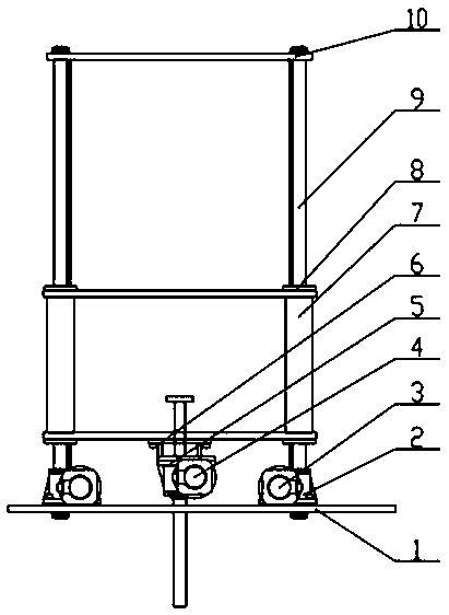
[0021] Such as figure 1 As shown, the present invention discloses a lifting mechanism for a stacking device of a direct-drive wind power stator core automatic stacking machine, including a Z-axis lifting unit, an S-axis lifting unit, a bottom plate 1 and a top plate 10, wherein the Z-axis lifting unit is arranged on the bottom plate 1 and the top plate 10, the S-axis lifting unit is arranged on the Z-axis lifting unit, the Z-axis lifting unit is used for the overall lifting of the stacking device, and the S-axis lifting unit is used for the lifting of the silicon steel sheet.

[0022] Such as figure 1 As shown, preferably, the Z-axis lifting unit includes a first screw lifter 2, a first motor 3, a moving frame 7, a guide post 8 and a guide sleeve 9, and the four corners of the bottom plate 1 are respectively fixed with the lower ends of the guide post 8, Wherein the upper end of guide column 8 is fixedly installed on the four corners of top plate 10, and described first screw...

Embodiment 2

[0038] Such as figure 1 As shown, the first screw lifter 2 and the first motor 3 are installed on both sides of the base plate 1, wherein the first screw lifter 2 is electrically connected to the first motor 3, and the first screw lifter is installed on both sides of the base plate 1, which can ensure The lifting of the mobile frame 7 is more stable and fast, which improves the overall production efficiency.

[0039] Four sets of first screw lifters 2 and first motors 3 can be installed around the base plate 1, and the number of first screw lifters 2 can be selected according to needs.

[0040] The working principle of the present invention is as follows:

[0041] When lamination is started, the first motor 3 drives the first screw lifter 2 to move the moving frame 7 up and down to determine the height of the stack. When the first motor 3 and the first screw lifter 2 act, the moving frame 7 and guide The sleeve 8, the connection seat 6, the second screw lifter 5 and the seco...


PUM


Abstract

The invention discloses a lifting mechanism of a sheet laminating device in an automatic sheet laminating machine for a direct-driven wind turbine stator iron core. The lifting mechanism comprises a Z-axis lifting unit, an S-axis lifting unit, a bottom plate (1) and a top plate (10). The Z-axis lifting unit is arranged between the bottom plate (1) and the top plate (10), the S-axis lifting unit isarranged on the Z-axis lifting unit, the Z-axis lifting unit is used for overall lifting of the sheet laminating device, and the S-axis lifting unit is used for lifting of silicon steel sheets. The lifting mechanism is provided with the two lifting units, the Z-axis lifting unit is used for overall lifting of the sheet laminating device, the S-axis lifting unit is used for lifting of the siliconsteel sheets, the two lifting units work simultaneously, and the heights of the sheet laminating device and the silicon steel sheets are adjusted according to the sheet laminating process, so that thesilicon steel sheets can be more rapidly sucked to be laminated, the sheet laminating time is shortened, and the overall production efficiency is improved.

Description

technical field [0001] The invention belongs to the field of stator core manufacturing, in particular to a lifting mechanism for a lamination device of a direct-drive wind power stator core automatic lamination machine. Background technique [0002] At present, the production of domestic direct-drive wind power stator cores is completed by workers manually stacking silicon steel sheets. In order to reduce the manufacturing cost of direct-drive wind power stator cores and improve production efficiency, an automatic direct-drive wind power stator core lamination machine is needed. To complete the lamination action, the lamination device in the automatic lamination machine is required. Since the diameter and weight of the direct drive wind power stator core are too large to move, the lamination device is needed to complete the lamination process. The silicon steel sheets need to be stacked layer by layer on the stator to form the stator core. Therefore, a lifting mechanism is r...

Claims


Application Information

Patent Timeline
Patent Type & Authority Applications(China)
IPC IPC(8): B66F7/14B66F7/28
CPCB66F7/14B66F7/28
Inventor 崔有成王忠平
Owner CECEP XIAN QIYUAN MECHANICAL & EIECTRICAL EQUIP CO LTD
Why Eureka
Try Eureka