Multi-break switch and well lid device

A technology of multiple switches and manhole covers, which is used in building locks, non-mechanical drive-operated locks, buildings, etc., can solve the problems of single structure and poor anti-theft function, and achieve the effect of ensuring safety, strong anti-theft function and diversified unlocking methods.

Active Publication Date: 2018-10-23
NINGBO HI-TECH DISTRICT RUIAO OPTOELECTRONIC TECH CO LTD
View PDF8 Cites 9 Cited by
  • Summary
  • Abstract
  • Description
  • Claims
  • Application Information

AI Technical Summary

Problems solved by technology

However, due to the high value of the cable, it has become the object of criminals stealing. Theft of underground cables occurs frequently. Poor, easy for criminals to take advantage of

Method used


Image

  • Multi-break switch and well lid device
  • Multi-break switch and well lid device
  • Multi-break switch and well lid device

Examples


Embodiment 1

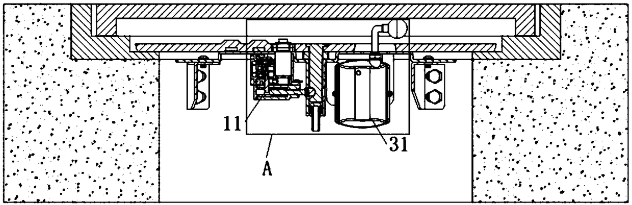
[0030] see figure 1 and figure 2 As shown, it is respectively the structural diagram and the closed state of a well cover device of the present invention figure 1 Enlarged view of middle A.

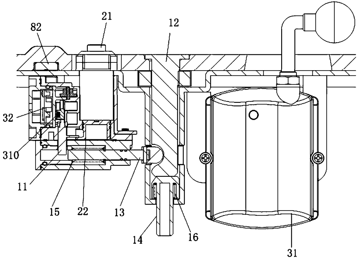
[0031] combine figure 1 and figure 2 As shown, a multiple switch lock includes a locking structure, a key switch structure and a motor clutch switch structure, the locking structure includes a drive shaft 11, and the drive shaft 11 is connected to the key switch structure and the motor clutch switch structure respectively , the motor clutch switch structure includes a monitor 31, a drive control board 32 and a motor clutch structure electrically connected in sequence, and the key switch structure and the motor clutch switch structure are opened only after passing an authorization procedure.

[0032] Among them, such as figure 2 As shown, the locking structure also includes a clamping shaft 12, a main shaft assembly 13 and a limiting block 14, and springs are connected to the main ...

Embodiment 2

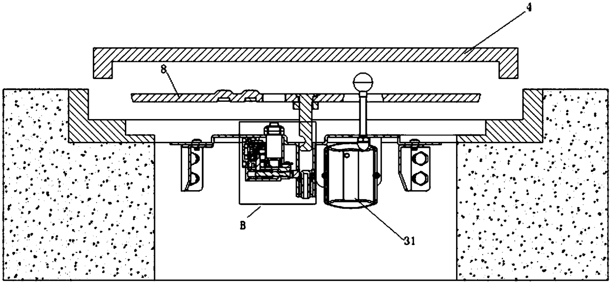
[0036] see image 3 and Figure 4 As shown, it is respectively the structural diagram and the image 3 Enlarged view of middle part B.

[0037] As a kind of multiple switch lock as mentioned above, the difference of this embodiment is that, as Figure 4 As shown, the key switch structure includes a lock cylinder 21 and a driving toggle block 22 that are connected to each other. The drive shaft 11 is provided with a first horizontal shaft 111, and the first horizontal shaft 111 is connected to the driving toggle block. 22, the lock cylinder 21 is a replaceable lock cylinder 21.

[0038] Such as Figure 4 As shown, when the multi-switch lock needs to be opened, insert the authorized electronic key into the lock cylinder 21 and rotate it clockwise by 90°, and simultaneously drive the driving toggle block 22 to rotate together. At this time, the drive shaft 11 The first horizontal axis 111 on the top moves upward along the rising platform on the driving toggle block 22, so th...

Embodiment 3

[0040] see Figure 5 to Figure 8 as shown, Figure 5 and Figure 6 Respectively, the structure diagram when the motor clutch switch structure is unlocked for a well cover device of the present invention, Figure 5 The magnified view of part C in the middle, Figure 7 and Figure 8 They are respectively the structural diagram of the motor clutch structure of a multiple switch lock in the closed state and the structural diagram in the open state of the present invention.

[0041] As a kind of multiple switch lock as mentioned above, the difference between this embodiment and the first embodiment is that, as Figure 7 As shown, the motor clutch structure includes a motor assembly 33, a first gear assembly 34, and a second gear assembly 35 that are meshed with each other in sequence. The second gear assembly 35 is provided with a connecting shaft 36, and the connecting shaft 36 is sleeved on A drive block 37 is provided, a drive spring 38 is provided between the drive block 3...


PUM


Abstract

The invention firstly provides a multi-break switch. The multi-break switch comprises a locking structure, a key switch structure and a motor clutch switch structure, wherein the locking structure comprises a drive shaft; the drive shaft is separately connected with the key switch structure and the motor clutch switch structure; and the motor clutch switch structure comprises a monitor, a drive control panel and a motor clutch structure which are electrically connected. The invention provides a well lid device which comprises a roadbed, a well base, an inner well lid assembly and an outer welllid, and further comprises the multi-break switch, wherein the well base is mutually fixed with the inner well lid assembly through the multi-break switch. According to the multi-break switch and thewell lid device provided by the invention, the multi-break switch is provided with the key switch structure and the motor clutch switch structure, so that unlocking ways are various, and use is moreintelligent and convenient. Moreover, the key switch structure and the motor clutch switch structure are opened after being subjected to authorized program, so that the anti-theft function of the multi-break switch is stronger, and therefore, financial safety in a well is guaranteed.

Description

technical field [0001] The invention relates to the technical field of well covers, in particular to a multi-switch lock and a well cover device. Background technique [0002] With the rapid development of urban economy and the improvement of the quality of urban life, underground cables have become a trend in the new century and new era. It has played a beneficial role in beautifying the urban environment and improving urban functions, and can also measure the modernization and scientific development of a city. high degree. However, due to the high value of the cable, it has become the object of criminals stealing. Theft of underground cables occurs frequently. Poor, it is easy for criminals to take advantage of it. [0003] In view of the above-mentioned defects, the creator of the present invention has finally obtained the present invention through long-term research and practice. Contents of the invention [0004] In order to solve the above problems, the technical ...

Claims


Application Information

Patent Timeline
Patent Type & Authority Applications(China)
IPC IPC(8): E05B65/00E05B63/00E05B47/00E05B15/00
CPCE05B15/00E05B47/0012E05B63/0065E05B65/006
Inventor 王志文黄志刚应超韦方俊
Owner NINGBO HI-TECH DISTRICT RUIAO OPTOELECTRONIC TECH CO LTD
Why Eureka
Try Eureka