
Relay and contact system thereof

A technology of relays and contacts, applied in relays, electromagnetic relays, contacts, etc., can solve the problems of violent material heating, adhesion, contact point welding, etc., and achieve the purpose of increasing the electric cross-sectional area, reducing contact welding, and reducing temperature rise Effect

Inactive Publication Date: 2018-10-23
JOHNSON ELECTRIC SHENZHEN
View PDF8 Cites 2 Cited by
  • Summary
  • Abstract
  • Description
  • Claims
  • Application Information

AI Technical Summary

Problems solved by technology

As a result, the material heats up violently where the current density is high and, due to the current intensity and duration of action, welding of the contact points and thus undesired sticking can occur

Method used


Image

  • Relay and contact system thereof
  • Relay and contact system thereof
  • Relay and contact system thereof

Examples


Embodiment Construction

[0032] The technical solutions and other beneficial effects of the present invention will be apparent through the detailed description of specific embodiments of the present invention below in conjunction with the accompanying drawings. It can be understood that the drawings are provided for reference and illustration only, and are not intended to limit the present invention. The dimensions shown in the drawings are only for the convenience of clear description, and do not limit the proportional relationship.

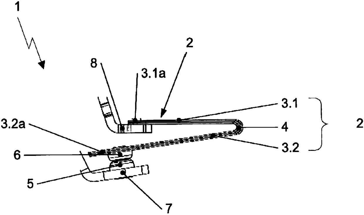
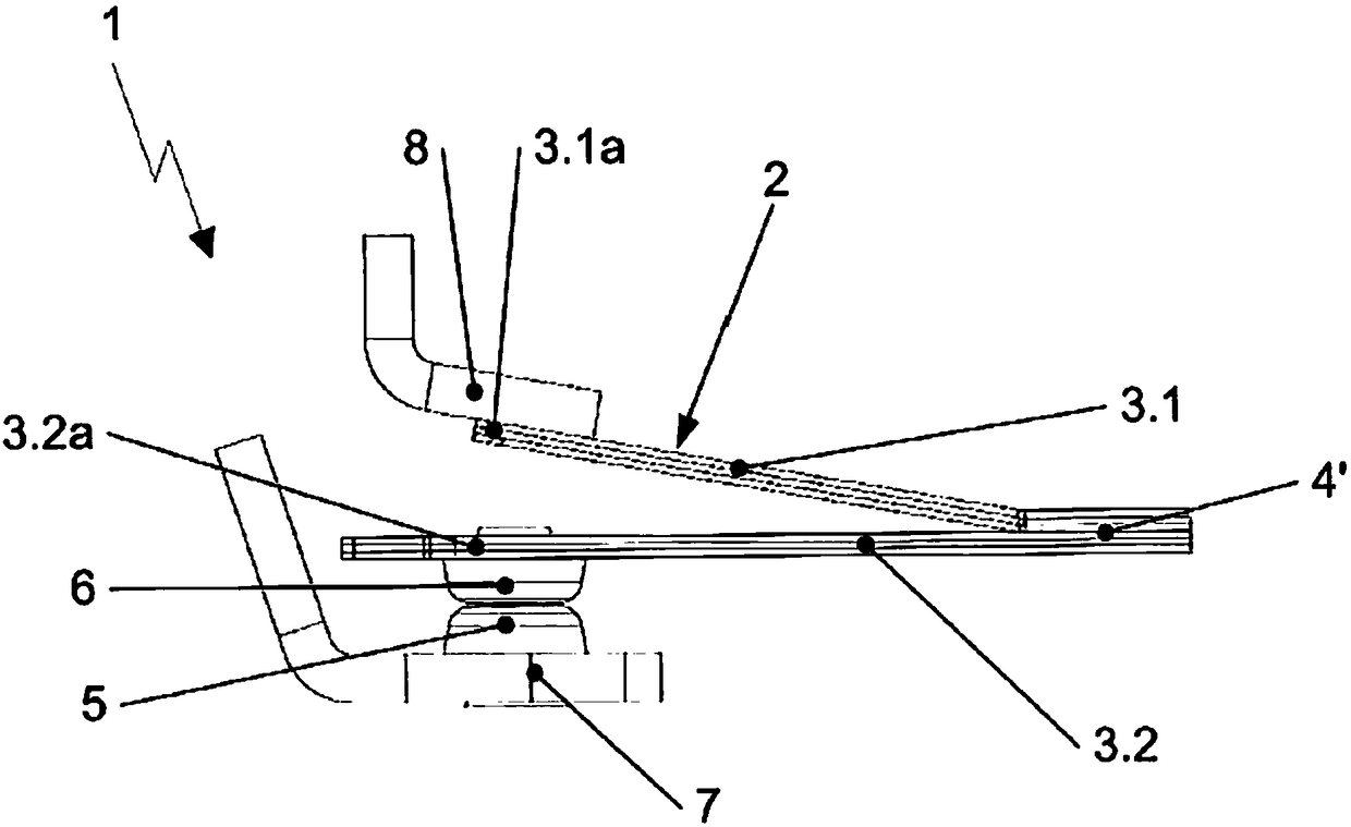
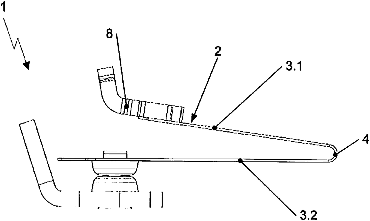
[0033] Please refer to Figure 1A , Figure 1A The contact system 1 of an off relay using a substantially V-shaped contact carrier 2 is shown. Wherein, the V-shaped contact bracket 2 includes two spring arms 3.1, 3.2, and the first upper spring arm 3.1 and the second lower spring arm 3.2 are connected to each other through a rounded connecting portion 4 . The contact system 1 serves to switch the contact between a first stationary fixed contact part 5 and a second mova...


PUM


Abstract

The invention discloses a contact system, and the system includes at least one contact pair and a flexible contact support. The contact pair includes a fixed contact piece connected to a first conductor rail and a moveable contact piece. The flexible contact support includes first and second spring limbs connected to each other via a connection. An end of the first spring limb connected to a second conductor rail and the moveable contact piece attached on the second spring limb. The opposing first and second spring limbs extending from the connection form a sharp angle V-shaped configuration.The contact support may be formed of a single piece or of a multi-piece design. The contact support may, in the connection area, be formed of two spring limbs arranged in parallel above one another and connected to each other.

Description

technical field [0001] The invention relates to a contact system which is particularly suitable for realizing the switching function in an off relay. Background technique [0002] The flexible contact bracket is usually suitable for the shut-off relay in the smart meter. The existing shut-off relay includes one or more pairs of contacts. One contact of the contact pair is fixed on the relay shell, and the other contact is a movable contact. Its movement is achieved by a flexible contact holder to which the movable contact is attached. Each contact pair is pressed against each other by a contact pressure, which is achieved by prestressing the flexible contact carrier relative to the relay housing. [0003] In particular, when the relay is used to switch off a large current, since the contact cannot be fully contacted on the entire surface, the current will not flow uniformly on the contact surface, but must flow through the point-like constriction, thereby producing the opp...

Claims


Application Information

Patent Timeline
Patent Type & Authority Applications(China)
IPC IPC(8): H01H50/56H01H50/54
CPCH01H50/54H01H50/56H01H1/26H01H1/50H01H1/54H01H1/28H01H2001/265
Inventor 马克思·赫尔曼艾瑞克·赫佐格
Owner JOHNSON ELECTRIC SHENZHEN
Learn More